What's new
  • ICMag with help from Landrace Warden and The Vault is running a NEW contest in November! You can check it here. Prizes are seeds & forum premium access. Come join in!

Philips 315w CDM Elite (CMH)

GrowerGoneWild

Active member
Veteran
Bummer about the phantom CMH ballasts, I was going to go that way but all the issues have got me spooked. I'm looking for a backup, and I'm going to expand with another CMH.

I like to buy ballasts local for that reason too. I can get a replacement the same day, because I dont have backup ballasts (yet).

The nanolux one I have has been working perfectly for the last few months.
 

Hammerhead

Disabled Farmer
ICMag Donor
Veteran
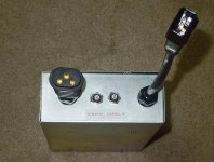
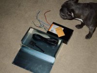
1st box is complete.. Tested it works fine. Next 1 is waiting for parts.
 

Attachments

  • DSCN4445.jpg
    DSCN4445.jpg
    87.8 KB · Views: 25
  • DSCN4446.jpg
    DSCN4446.jpg
    114.6 KB · Views: 19
Last edited:

Hammerhead

Disabled Farmer
ICMag Donor
Veteran
its just a standard power cord with c14-c13. You can get an adapter but the price is the same or more than a 6' cord. I wanted 1 that had 14g wire.

https://www.amazon.com/gp/product/B005WKJPBS/ref=oh_aui_detailpage_o01_s00?ie=UTF8&psc=1

Going this route if you dont have most of the parts already is not gonna be cheaper. I have most of the parts on hand. I never toss anything electrical. You never know what you might need later. I used up the 2 Push breakers I had so I needed to order 2 more witch was $10. $30 for the box. . 1st box was build cost 30$... Lamp cord adapter, Power cords, Eboots, spring lever wire terminals all on hand.
 
Last edited:

Jhhnn

Active member
Veteran
its just a standard power cord with c14-c13. You can get an adapter but the price is the same or more than a 6' cord. I wanted 1 that had 14g wire.

https://www.amazon.com/gp/product/B005WKJPBS/ref=oh_aui_detailpage_o01_s00?ie=UTF8&psc=1

Going this route if you dont have most of the parts already is not gonna be cheaper. I have most of the parts on hand. I never toss anything electrical. You never know what you might need later. I used up the 2 Push breakers I had so I needed to order 2 more witch was $10. $30 for the box. . 1st box was build cost 30$... Lamp cord adapter, Power cords, Eboots, spring lever wire terminals all on hand.

Thanks for that. The view threw me off somehow.
 

Hammerhead

Disabled Farmer
ICMag Donor
Veteran
2nd box is complete.. Pretty much the same as 1st box. Grounded the case in a better spot on this 1.
picture.php

picture.php
 

IntotheGreen

Active member
Very cool Hammerhead! Question - are these push breakers necessary to operate the ballast safely or just personal preference? This is the first time I've seen mention of them. Gonna be getting a couple of those boxes soon so I can finally start building up these systems - just wanna make sure I'm not missing anything. Looking back at the pic of Rives's now - is that what the two black buttons in the middle are?
 

Hammerhead

Disabled Farmer
ICMag Donor
Veteran
IMO there needed. Fusses would work as well. All of my old ballast use them. None are on the Gavita's.
 

rives

Inveterate Tinkerer
Mentor
ICMag Donor
Veteran
Very cool Hammerhead! Question - are these push breakers necessary to operate the ballast safely or just personal preference? This is the first time I've seen mention of them. Gonna be getting a couple of those boxes soon so I can finally start building up these systems - just wanna make sure I'm not missing anything. Looking back at the pic of Rives's now - is that what the two black buttons in the middle are?

As HH said, circuit breakers or fuses should be considered mandatory. Many devices don't have user-serviceable fusing, but the fuses are on the circuit board and the device has to be disassembled to access them. Yes, those are fuseholders that you see on my ballast - I prefer fusing because you can more closely match the rating to the load characteristics, but breakers are also fine.
 

Hammerhead

Disabled Farmer
ICMag Donor
Veteran
I'm sure Phillips ballast has protection built into the board but its not user serviceable like rives said.. If it did blow I would have to pop the case open and find the fuse. These can be real small like a pico fuse. Trouble shooting this can be a pain. Its just better to have protection before the device.They do have a wide selection of push breakers amps. I was going to go with 10a but 15a won lol..
 

positivity

Member
Veteran
I'm running the single 315w version right now. Picked it up off of alibaba though. Will see if it lasts the grow
So far so good, the remote works well, gets a little hot
 

positivity

Member
Veteran
I'm running the single 315w version right now. Picked it up off of alibaba though. Will see if it lasts the grow
So far so good, the remote works well, gets a little hot

edit..browser bugged out, sorry about the double post.
 

IntotheGreen

Active member
Good info as always guys, thanks! How are the breakers/fuses wired in? One on input side, one on output? Or one on each hot leg of incoming power?

Also have a question about connecting the timer in this system - not the internal wiring of contacts per se but from power to timer/timer to transformer. I'm planning to use the T103, which (correct me if I'm wrong) being DPST should let me switch (2) 120v loads simultaneously, so transformer -> ballasts/lamps plus fans. I want to clarify how to actually connect the separate devices.

Being in an apt I really can't rip into the walls and run a new circuit direct from breaker to timer, so everything has to run off the existing 15A wall receptacle. I assume I would therefore need to hardwire a standard 14g 120v power cord to timer and plug male end into wall receptacle? Then as far as getting power from timer to the transformer/fans, I guess it would make most sense to wire two separate receptacles to the load contacts, possibly in a box attached directly to the timer, into which I would plug transformer cord and power strip/fans. Does that sound right?
 

Jhhnn

Active member
Veteran
The newer 120v ballasts offer some easy ways of doing things. The ballasts draw 340-350 watts, less than 3A, so quality household 1/2 HP timers (373W inductive load) work just fine. I use a GE 15075 on my garden seedling setup. If you want more lights, just use more timers up to 4 on a dedicated 15A breaker.
 

Hammerhead

Disabled Farmer
ICMag Donor
Veteran
Good info as always guys, thanks! How are the breakers/fuses wired in? One on input side, one on output? Or one on each hot leg of incoming power?

Also have a question about connecting the timer in this system - not the internal wiring of contacts per se but from power to timer/timer to transformer. I'm planning to use the T103, which (correct me if I'm wrong) being DPST should let me switch (2) 120v loads simultaneously, so transformer -> ballasts/lamps plus fans. I want to clarify how to actually connect the separate devices.

Being in an apt I really can't rip into the walls and run a new circuit direct from breaker to timer, so everything has to run off the existing 15A wall receptacle. I assume I would therefore need to hardwire a standard 14g 120v power cord to timer and plug male end into wall receptacle? Then as far as getting power from timer to the transformer/fans, I guess it would make most sense to wire two separate receptacles to the load contacts, possibly in a box attached directly to the timer, into which I would plug transformer cord and power strip/fans. Does that sound right?

With any 240v device you need to protect ea hot leg on the 240v line.

If it was a 120v device only 1 breaker/fuss is needed.

On the back of the breaker you we see line/load. Power hot goes to line terminal on breaker. Breakers Load out goes to device hot line in... :tiphat:
 
Last edited:

rives

Inveterate Tinkerer
Mentor
ICMag Donor
Veteran
Good info as always guys, thanks! How are the breakers/fuses wired in? One on input side, one on output? Or one on each hot leg of incoming power?

Also have a question about connecting the timer in this system - not the internal wiring of contacts per se but from power to timer/timer to transformer. I'm planning to use the T103, which (correct me if I'm wrong) being DPST should let me switch (2) 120v loads simultaneously, so transformer -> ballasts/lamps plus fans. I want to clarify how to actually connect the separate devices.

Being in an apt I really can't rip into the walls and run a new circuit direct from breaker to timer, so everything has to run off the existing 15A wall receptacle. I assume I would therefore need to hardwire a standard 14g 120v power cord to timer and plug male end into wall receptacle? Then as far as getting power from timer to the transformer/fans, I guess it would make most sense to wire two separate receptacles to the load contacts, possibly in a box attached directly to the timer, into which I would plug transformer cord and power strip/fans. Does that sound right?

As HH said, the fuses go into each hot leg.

Your scenario is correct, but if you are only feeding the T103 with a single circuit, then the double-pole configuration doesn't buy you anything other than reducing the switching current on each contact.

The newer 120v ballasts offer some easy ways of doing things. The ballasts draw 340-350 watts, less than 3A, so quality household 1/2 HP timers (373W inductive load) work just fine. I use a GE 15075 on my garden seedling setup. If you want more lights, just use more timers up to 4 on a dedicated 15A breaker.

What you are describing will certainly work for a while, but electronic ballasts are capacitive, not inductive, loads. Capacitive loads are much more difficult to switch than even inductive ones, with inrush current being roughly equivalent to a short-circuit. The inrush current can approach 100x the steady-state current draw and takes place while the contacts are still bouncing. Capacitive loads are THE most difficult to switch reliably.
 

Jhhnn

Active member
Veteran
As HH said, the fuses go into each hot leg.

Your scenario is correct, but if you are only feeding the T103 with a single circuit, then the double-pole configuration doesn't buy you anything other than reducing the switching current on each contact.


What you are describing will certainly work for a while, but electronic ballasts are capacitive, not inductive, loads. Capacitive loads are much more difficult to switch than even inductive ones, with inrush current being roughly equivalent to a short-circuit. The inrush current can approach 100x the steady-state current draw and takes place while the contacts are still bouncing. Capacitive loads are THE most difficult to switch reliably.

Capacitive loads can be difficult, depending on the size of the capacitors. I'm not equipped to measure the inrush current for ballasts of any kind or the waveforms created in the process. OTOH, I've yet to see a capacitive load rating on any timer or any information about that wrt ballasts, either. I'm not sure what that would look like.

I don't think either one of us would bat an eye if somebody said they intended to run four 120v 315 ballasts on a T-100 series 2hp timer even though the safety factor in terms of rating would be the same as one 315 ballast on a 1/2hp timer.

Just food for thought my friend.
 

rives

Inveterate Tinkerer
Mentor
ICMag Donor
Veteran
Capacitive loads can be difficult, depending on the size of the capacitors. I'm not equipped to measure the inrush current for ballasts of any kind or the waveforms created in the process. OTOH, I've yet to see a capacitive load rating on any timer or any information about that wrt ballasts, either. I'm not sure what that would look like.

I don't think either one of us would bat an eye if somebody said they intended to run four 120v 315 ballasts on a T-100 series 2hp timer even though the safety factor in terms of rating would be the same as one 315 ballast on a 1/2hp timer.

Just food for thought my friend.

You are right that I wouldn't hesitate to run (4) 315's on a T-100. However, that is because the T-100 has an electronic ballast rating of 16a @ 277v. The 120v ballasts might send me on a quest for more information, though.

While it can give the user some indication, it really isn't possible to accurately extrapolate a device's current rating from one type of load to another. A given device may be designed to reliably switch one type of load, but the design may inherently be unsuitable for another. Low-amperage DC loads, for instance, need a "wiping" action at the contacts to minimize the buildup of an insulating oxidation of the contacts while higher-amperage DC needs blow-out magnets or coils to extinguish the arc and a straight contact actuation. Many loads require specific design criteria that may be irrelevant, or even incompatible, with other applications.

If you look at the specifications tab on the following link, you will see the T-100 series carries a 40a rating for resistive, inductive, and tungsten loads; drops to 24-28a for motor loads; and drops further to 16a for electronic ballasts.

http://www.intermatic.com/en/products/timeswitches/mechanicalswitches/24hour/t100series
 
Last edited:
Top