-
ICMag with help from Landrace Warden and The Vault is running a NEW contest in November! You can check it here. Prizes are seeds & forum premium access. Come join in!
You are using an out of date browser. It may not display this or other websites correctly.
You should upgrade or use an alternative browser.
You should upgrade or use an alternative browser.
Growroom Electricity and Wiring
- Thread starter Phillthy
- Start date
ok. first let me start by saying what a great site this is. ive been lurking for about a year now.
heres my question. im wanting to run 3x1000w hps. in my main panel ive got a 240v 30amp breaker with 10-3 w/ground running to my grow room. my original plan was to get a helios light controller and hook that up. after reading some comments about how the ballast cords are only rated for 15a and if something happens the breaker might not trip and that they are not meant for residential it got me wanting something safer.
I was thinking maybe I should change the breaker to 240v 20a. leave the 10-3 and feed that into a 240v 30a intermatic water heater timer and have the timer turn on 2 outlets. is this safe? will the breaker trip if if something happens? if not how can I make sure ive got a safe setup as I don't really want to burn my house down.
thanks
If you downsize the existing 30a breaker to 20a and feed the downstream circuitry with that, yes, it would be safe. This will work if you plan on running your 3kw on 240v, but if they are fed with 120v, the current will be too high. The 80% rule would allow you 16 amps (you are only allowed 80% of the breaker rating for continuous loads, which are defined as anything over 3 hours in duration). You also have to account for the ballast losses, so an estimate of an additional 10% load equals 3300 watts, or 13.75 amps at 240v.
Another option would be to keep the existing 30a breaker, feed the Intermatic with that, and then feed into a small sub-panel downstream of the timer. Small subs are available for under $20, and then you could break out the circuits with individual protection for each receptacle.
Keep in mind that the Intermatics, while bulletproof, are motor-driven and cannot be battery backed (there are some electronic models available, but they aren't nearly as common), and will lose their setting if the power goes off. They also have poor resolution because of the timer flippers, but good repeatability. An option would be to use a 40a power relay and control it with a conventional battery-backed digital timer.
This is the power relay that I normally recommend - http://www.automationdirect.com/adc...n-Style,_40A_(AD-PR40_Series)/AD-PR40-2C-120A
thanks for the reply rives. ive been racking my brain for 3 days over my electrical. im in the tile trade and remodeling comes easy to me except electrical. anything over 120v scares the shit out of me.
I wanted everything to run at 240v.so if I wanted to keep my 240v 30a breaker and run it into the intrematic then into a small subpanel.
1-should I use a 30a or 40a intermatic?
2-is 10-3 w/ground the right wire or do I need 10 -2 to run from the breaker to the timer?
3-from the timer to the subpanel use the same wire as from breaker to to timer?
4-the subpanel gets a 30a main breaker? and I could run 4x240v 15a to each outlet. 1x1000w per outlet
5- does the subpanel get wired up just like any other subpanel meaning grounds separate from common with common not making contact with box?
Just a note of caution on being comfortable with 120v vs the others - there are more people killed annually by 120v than ALL other voltages combined....
1) I don't recall ever seeing a 30a Intermatic other than possibly one of the electronic models (dim & distant memory!). The T-102 is the 240v motorized version that is commonly available, and it carries a 40a resistive rating. Bear in mind that resistance loads are the easiest ones to switch and so that is the rating that is normally advertised. I can't find a ballast load rating for the 100 series timers, but they will handle a 5 hp 240v motor which is a hell of a test. Personally, I would always go with the heaviest model available.
2) 10/3 is fine. The timer itself will not use the 3rd (neutral) wire, but it can be carried on through to the sub and then 120v will be accessible as well as 240v.
3) Yes. Tie the neutrals together in the timer, and then land it on the neutral buss in the sub for 120v.
4) Many subs do not have main breakers, but it might be handy to have one so you can dump everything with one switch vs turning off individual breakers. If you go with a main breaker in it, then a 30a unit will make the full capacity of the circuit available or it could be downsized. There wouldn't be much reason to downsize it if you have individual breakers protecting the branch circuits.
5) Yes. The ground and the neutrals should only be bonded together at the main panel - everywhere else, they should be isolated from each other. You will need to check whatever sub you buy, many of them require a separately purchased buss so that you can provide isolation.
I honestly like your original idea better because it's simpler, cheaper & easier if you only want to run three 1000w rigs. The most you can do with a 30A feed is 5.
Once the main breaker in your panel is off, the only part that has power is where the power comes in from the pole, usually at the top. It's a very straightforward operation to swap the 30A breaker for a 20A. When you have the new breaker in your hand you'll understand how it mounts to the buss bars.
Having recently helped a friend wire a grow, I can say that what you want is either an Intermatic T103, T104 or GM40AV timer. 240v is really just two 120v feeds that are 180 degrees out of phase so you want to switch both of them using DPST (double pole single throw) contacts. Details-
http://www.intermatic.com/en/products/timeswitches/mechanicalswitches/24hour/t100series
http://www.intermatic.com/en/products/timeswitches/electromechanicalswitches/gm40avseries
You can use a T103 w/ 125v clock motor because you have a 4 wire 240v feed.
Although the electrical code specifies that the same gauge wire be used throughout the circuit, it's safe to use #12 from the timer to the receptacles having a 20A breaker. It's much easier to work than #10. Rives might disagree on principle. He's the real electrician.
Good quality receptacles-
http://www.westsidewholesale.com/le...gle_Shopping&gclid=COG-sIv_5skCFQ8taQod6gUP_Q
You'll need 240v ballast cords, like this-
http://www.joeshydro.com/240-volt-p...m=9JH-BPC140&gclid=CMzNs9iX58kCFQyPaQod8L4Ivw
The sources are just what I grabbed from google.
I honestly like your original idea better because it's simpler, cheaper & easier if you only want to run three 1000w rigs. The most you can do with a 30A feed is 5.
Once the main breaker in your panel is off, the only part that has power is where the power comes in from the pole, usually at the top. It's a very straightforward operation to swap the 30A breaker for a 20A. When you have the new breaker in your hand you'll understand how it mounts to the buss bars.
Having recently helped a friend wire a grow, I can say that what you want is either an Intermatic T103, T104 or GM40AV timer. 240v is really just two 120v feeds that are 180 degrees out of phase so you want to switch both of them using DPST (double pole single throw) contacts. Details-
http://www.intermatic.com/en/products/timeswitches/mechanicalswitches/24hour/t100series
http://www.intermatic.com/en/products/timeswitches/electromechanicalswitches/gm40avseries
You can use a T103 w/ 125v clock motor because you have a 4 wire 240v feed.
Although the electrical code specifies that the same gauge wire be used throughout the circuit, it's safe to use #12 from the timer to the receptacles having a 20A breaker. It's much easier to work than #10. Rives might disagree on principle. He's the real electrician.
Good quality receptacles-
http://www.westsidewholesale.com/le...gle_Shopping&gclid=COG-sIv_5skCFQ8taQod6gUP_Q
You'll need 240v ballast cords, like this-
http://www.joeshydro.com/240-volt-p...m=9JH-BPC140&gclid=CMzNs9iX58kCFQyPaQod8L4Ivw
The sources are just what I grabbed from google.
this helps a lot. thanks
thanks again rives. you have cleared up a bunch of questions I had and im sure ill have some more if you don't mind me asking.
Ask away.
Yes, 10 gauge into conventional receptacles would be a pain in the ass.
Both arrangements will work, and undoubtedly lots more variations as well. It all depends on what you want to do, how much flexibility you want later, what other equipment you want to run, etc.
So I'm gonna be hooking up a powerbox dpc-4000. It has 2 available configs. 3 wire (2 hots + neutral) or 4 wire (2 hots, neutral, and ground). Have to install a 30a double pole breaker and run some wire from my panel. What would you guys recommend...3 or 4 wire? Gonna go with 10ga wire. Also...do I need a gfci breaker or just regular? The only thing being plugged into this line is my powerbox
If you are running a new circuit, it doesn't make any difference which way you go. The controller is for 240v, and the neutral is unused. They probably make the connection optional to ease the installation if you have an existing 3- or 4-wire receptacle.
A GFCI might save you from doing the 60-cycle shuffle if you have a grounding issue with one of your hoods.
Just so you know, I haven't had one apart to verify it, but the information from Powerbox doesn't show any additional fusing to protect the 15a receptacles and downstream devices that will be fed with up to 30 amps.
If you are running a new circuit, it doesn't make any difference which way you go. The controller is for 240v, and the neutral is unused. They probably make the connection optional to ease the installation if you have an existing 3- or 4-wire receptacle.
A GFCI might save you from doing the 60-cycle shuffle if you have a grounding issue with one of your hoods.
Just so you know, I haven't had one apart to verify it, but the information from Powerbox doesn't show any additional fusing to protect the 15a receptacles and downstream devices that will be fed with up to 30 amps.
What controller would you recommend? Titan helios 5? I'm not trying to go over the 200 dollar mark.
I haven't seen any commercially-available controller that includes the correct protection - they are all in competition with one another, and all cut the same corners to stay competitive.
A dryer/range cordset feeding an Intermatic T-104, and then feeding into a small sub-panel would be cheaper and give you the correct protection. The T-104 is rated at 40a, and the sub can break the circuit down correctly with 15a breakers for your downstream lighting circuits.
The only downside to this is, as I mentioned up above, that the T-104 is a motor-driven timer and will lose it's setting if you are prone to power outages. A DPDT power relay driven by an electronic timer is an option if you want electronic timing accuracy and battery backup.
So I'm gonna be hooking up a powerbox dpc-4000. It has 2 available configs. 3 wire (2 hots + neutral) or 4 wire (2 hots, neutral, and ground). Have to install a 30a double pole breaker and run some wire from my panel. What would you guys recommend...3 or 4 wire? Gonna go with 10ga wire. Also...do I need a gfci breaker or just regular? The only thing being plugged into this line is my powerbox
I'd run 10/3 w/ ground, even if you don't plan on using the neutral. The price difference is minimal & you have the option of using 120v accessories on the same circuit.
Can i run a T104 with 12/2 wire from a 20 amp breaker? The lights are 240v for a total of 9 amps but timer is rated at 40 amps.
Yes. Flag the white wire w/ red electrical tape at the terminations as a telltale for the future.
The timer can handle up to 40 amps so you'll be golden.
As above, I strongly encourage people to run 3 conductor cable w/ ground on new 240v wiring. Even if you're not planning on it, you can then easily create 120v outlets on the same circuit- always hot &/or switched with the lights if you want. It's particularly handy for two stage ventilation- see the ventilation 101 thread.
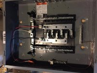
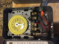
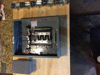
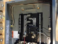
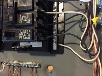
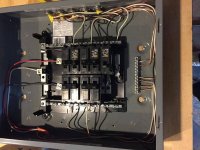
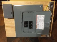
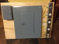
hey guys just an update. after talking to you guy and thinking it over I left the 30a 240v circuit and built a light controller. if I post some pics can you guys look at them and make sure you don't see anything wrong.
I took the 10-3 from the circuit breaker into a t103 timer. 10-3 from timer to the subpanel. 4x15a 240v breakers wired to the outlets with 12-2. and 1 20a 120v breaker wired to outlet with 12-2. I used 12-2 cause I had a lot of it laying around and didn't want to buy more. the 20a 120v breaker is cause it came with the sub panel.i added it incase I wanted to run a fan or something when the lights turn on.
I took the 10-3 from the circuit breaker into a t103 timer. 10-3 from timer to the subpanel. 4x15a 240v breakers wired to the outlets with 12-2. and 1 20a 120v breaker wired to outlet with 12-2. I used 12-2 cause I had a lot of it laying around and didn't want to buy more. the 20a 120v breaker is cause it came with the sub panel.i added it incase I wanted to run a fan or something when the lights turn on.
Attachments
It looks great!
I can't tell from the pictures well enough to tell for sure what they are, but it looks like about half way down the neutral buss on each side, there is a dark screw in place. These look like they are mounting screws, but sometimes a green screw is used to go through the buss and back into the sheet metal of the panel, bonding the neutral to ground. If that is the case, this should be removed - a sub panel DOES NOT have the neutral and ground bonded, only a main panel does that. There should only be one place in the entire electrical installation where the neutral and ground are tied together, and that is at the main.
The white wires on the double-pole breakers feeding your 240v plugs should be "phase taped" - wrapped with red or black tape to denote that they are being used as hot wires, not as neutrals. White is reserved for neutral usage only.
If you wind up with a significant 120v load, you might want to add another single-pole breaker on the other phase so that you can balance the load between the phases as much as possible.
Nice job.
thanks rives. I had a little electrical experience and I read for 3-4 days to understand everything. you and jhhnn helped me out answering the questions I had and couldnt figure out or didn't want to guess at. so thanks again to both of you.
I think what you are seeing is the plastic tabs holding the neutral bus to the plastic piece that isolates the bus from the case. they included a big green screw to bond the bus to the case but I did not use it and I looked to make sure it wasn't bonded anywhere else but I will double check that tomorrow.
I didn't know the wires needed to be phase taped and honestly I wont be doing it. if I move this panel will be coming with me and no one else will be working on it. if it was staying with the house I would tape them.
I doubt I will ever use the 120v outlet but I liked the idea of having incase later down the road. I will keep in mind to try and have balanced loads if I use the outlet for a heavy load.

