What's new
  • As of today ICMag has his own Discord server. In this Discord server you can chat, talk with eachother, listen to music, share stories and pictures...and much more. Join now and let's grow together! Join ICMag Discord here! More details in this thread here: here.

Philips 315w CDM Elite (CMH)

Is that post to me or rives?

If it's to me, I don't know enough about that to know if I like it or not. I really don't know jack about electronics. I rely on people I trust to tell me if something fits my needs.

But from what I can tell (and I may be wrong), it doesn't suite my needs because I want to be able to choose what % I dim to in an easy way. So for example, I want to push a button or turn a knob to a specific % dim, like choose 50%, 60%, 70%, etc. Because if I know the % I dim to I know the PPF at canopy because the PPF at 100% is very well defined (at any height from the floor between the bottom and top irradiance planes) using Greenbeams modeled by LTIOptics.

For example, if I dim to 70% I know the PPF at canopy (at any point between the two irradiance planes) without measuring with my quantum sensors, so I know the DLI as well. However, if I just dim without knowing the % of total energy I'm dimming to, I need to test with my quantum sensors to know the PPF and DLI.
 
Last edited:

rives

Inveterate Tinkerer
Mentor
ICMag Donor
Veteran
I was stream of consciousness posting I guess.

I meant to ask if a straight rheostat 120VAC wall dimmer would work for our 0-10V DC needs. Would it?

From the tone of your last post, it sounds like BTT answered your question. For anyone still confused, no, a straight rheostat will not work.

For people that are somewhat familiar with using a meter, it's pretty simple to build up a voltage divider circuit and use a cell-phone power supply or equivalent. Many of them have a nominal voltage rating of around 9 volts, but that is under full load. Under no-load conditions, or the very light load from these ballasts, the voltage will frequently be in the 11-13v range.
 

HorseBadoritiz

Active member
Ballast Orientation

Ballast Orientation

I see on the double d pap that the integrated ballast is mounted vertically. I've heard it's because the heat is dissipated better out the end vs being trapped inside a horizontal case?

I'm remotely running an e-Vision kit from Advanced which has no venting that I can see, but I'm wondering if there's a best orientation for mounting it?

Thanks!
 

rives

Inveterate Tinkerer
Mentor
ICMag Donor
Veteran
The Philips ballasts put out so little heat that it is really nothing to concern yourself about. The ballast power consumption is only 26 watts, and they barely get to body temperature. I haven't used any of the other brands, so they may be different.
 

Ericos

Member
I see on the double d pap that the integrated ballast is mounted vertically. I've heard it's because the heat is dissipated better out the end vs being trapped inside a horizontal case?

I'm remotely running an e-Vision kit from Advanced which has no venting that I can see, but I'm wondering if there's a best orientation for mounting it?

Thanks!

Rives is right. Ballast doesnt heat up like most. I mounted my ballast on my hoods and they're still just warm to the touch.
 
It's true the ballasts are cooler than others due to the low wattage draw of the e-Vision ballast, but for dozens (or greater) of ballasts in a room the additional heat load is something to consider to optimize energy efficiency (in terms of cooling).

What I really like about the Gel Ceramatek is their wattage draw is only 16 watts, as well as increased lamp useful life span.

The dPapillion seems to use the Philps e-Vision ballast as it's claimed wattage draw is 25 watt, even though e-Vision is listed at 24 watts. But the Double dPapillion ballast has a wattage draw of about 60 watts (which is pretty close to the wattage draw of newer digital HPS ballasts).
 
Last edited:
Looking at the dPapillion product lit. they're claiming 92% efficiency of the reflector, which isn't true if they're referring to PAR range umol/s (it's close to 85% over PAR range, I have the exact value but don't feel like looking it up right now).

What I like about the Double dPapillion is the dimming feature, at 50%, 70%, and 85%. Interestingly, the product lit. for the Double dPapillion doesn't make the same claim about 92% reflector efficiency that's made in the lit. for the dPapillion.

And the claim about 16K hours for >90% of initial umol/s in PAR range is not correct, at least not according to Philips specs. for the Greenpower 315W lamp and MasterColor 942 lamp.

What I don't like about the Double dPapililion is the ballast attached to the fixture...
 

HUGE

Active member
Veteran
I am getting them from a local hydro store. PHive.8 is the USA distributor I believe.
 

Avenger

Well-known member
Veteran
From the tone of your last post, it sounds like BTT answered your question. For anyone still confused, no, a straight rheostat will not work.

For people that are somewhat familiar with using a meter, it's pretty simple to build up a voltage divider circuit and use a cell-phone power supply or equivalent. Many of them have a nominal voltage rating of around 9 volts, but that is under full load. Under no-load conditions, or the very light load from these ballasts, the voltage will frequently be in the 11-13v range.

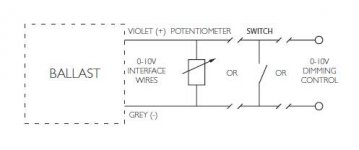
the 0-10 volt dimming feature of the Phillips ballast needs only a current sinking control, not a current source for the control.

So yes a potentiometer will work for the dimming control. You can even tie multiple fixtures together, but you have to consider the current from each dimming ballast control circuit and make sure the control is made for it. iirc each ballast dimming control circuit on the Phillips is "Maximum dimming control current is 0.5 mA per ballast"

so for one ballast, you need 10K ohms resistance to sink 5 volts and tell the ballast to dim to 75% output

but for two ballast connected to the same dimming controller, you only need 5k ohms to tell the ballasts to dim to 75% output

At least that is how I think ohms law works, it has been a while since I applied it. So please do correct me if my calculations are incorrect. Always double check my math.


attachment.php


The 0-10 volt dimmers like the Lutron brand or the Cooper industries brand are usually good for more than one ballast, but you will have to check the rating on the specific one you consider to know how many. I have seen them rated at any where from 20 milliamps to 200 milliamps.

But these don't give the accuracy that BTT is looking for, or the digital read out. For those features, I think something like this fancy digital potentiometer would work nicely.

Cheers, rives. :sasmokin: you do good work here.
 

Attachments

  • 0-10 volt dimming control wire schematic, Philips.jpg
    0-10 volt dimming control wire schematic, Philips.jpg
    8.8 KB · Views: 21

Ericos

Member
Off track a liitle on the dimming talk. Me personally, and financially, have to piece a lot together but cost savings and results are showing for me for, subjectively.

Can't wait for beta's greenbeam setup!

Girls of all ages in their lives in the beginning of the ends!!! 315s. The stalky one is the oldest and newest in there, hehehe. Those in the back are about 6"-8" from the bulb and happy as hell.
 

rives

Inveterate Tinkerer
Mentor
ICMag Donor
Veteran
I think that some of the above discussion was edited prior to your arrival, Avenger.

Yes, the Philips ballast is a sinking design, but there is no built-in 10vdc signal to provide the power for a standalone circuit to work. A rheostat is used for conventional incandescent dimming control and works by inserting resistance between the voltage source and the lamp. As resistance is added, the lamp dims. They have only two wiring connections and this device is what LP was originally referring to - "I meant to ask if a straight rheostat 120VAC wall dimmer would work for our 0-10V DC needs. Would it?"

A potentiometer is used to create a voltage divider, and has three wire connections - ground attaches to one end of the resistor, the positive voltage attaches to the other end of the resistor, and the wiper functions as the voltage divider signal and, in this case, would go to the (+) Dim input on the ballast. This would work well except for the absence of a positive voltage source on the ballast to feed the circuit. This can come from a controller like the one LP linked, or can be pieced together as I mentioned via a wall wart. However, I found that a trimming resistor would usually need to be added in order to keep the voltage range within the ballast's specifications when using the cheap power sources.
 

Jhhnn

Active member
Veteran
I think that some of the above discussion was edited prior to your arrival, Avenger.

Yes, the Philips ballast is a sinking design, but there is no built-in 10vdc signal to provide the power for a standalone circuit to work. A rheostat is used for conventional incandescent dimming control and works by inserting resistance between the voltage source and the lamp. As resistance is added, the lamp dims. They have only two wiring connections and this device is what LP was originally referring to - "I meant to ask if a straight rheostat 120VAC wall dimmer would work for our 0-10V DC needs. Would it?"

A potentiometer is used to create a voltage divider, and has three wire connections - ground attaches to one end of the resistor, the positive voltage attaches to the other end of the resistor, and the wiper functions as the voltage divider signal and, in this case, would go to the (+) Dim input on the ballast. This would work well except for the absence of a positive voltage source on the ballast to feed the circuit. This can come from a controller like the one LP linked, or can be pieced together as I mentioned via a wall wart. However, I found that a trimming resistor would usually need to be added in order to keep the voltage range within the ballast's specifications when using the cheap power sources.

This is a nice chopper type regulated supply that I've used for different projects-

http://www.powerstream.com/ac-09013.htm

9V won't quite give full range dimming, but output voltage remains constant at any load so no trimmer resistor is required.
 

Avenger

Well-known member
Veteran
the absence of a positive voltage source on the ballast to feed the circuit.

so you are telling me the grey and purple wires do not have 10 volts DC potential between them when the ballast is powered on?
 

Hottish

Active member
UVA & UVB Eye Protection

UVA & UVB Eye Protection

Anyone using safety glasses for UVA & UVB Protection when working under 315Ws , or does the T12 outer glass shield filter enough UVA & UVB to give protection

:tiphat:
 

rives

Inveterate Tinkerer
Mentor
ICMag Donor
Veteran
so you are telling me the grey and purple wires do not have 10 volts DC potential between them when the ballast is powered on?

I'm going by memory because I'm out of town, but as I recall from when I put my controller together, the Dim (-) on the ballast is used as a ground reference, and is used to tie the ballast ground to the dimming controller ground. The Dim (+) ballast input is looking for a signal per the chart that BTT posted. If it is floated (left disconnected), the lamp output is 100%. If it is clamped to ground, the lamp output is 50%.

On the installation where I used the dimming control, I used a single power supply feeding a resistor network that formed several voltage dividers and could be selected through via some ice cube relays. The PLC running things can then decide what lamp power to use based on ambient temperature or whatever.

Rives, i think there is. the purple (or grey) makes 10V at .25mA, right?

Again, if memory serves, the .25mA rating is the burden placed on the controller circuit and not what the ballast is capable of providing. So, if you are controlling (X) number of ballasts, the dimming controller circuit/power supply must be rated for (X)*.25mA.

In order for the dimming circuit to be controlled via a stand-alone potentiometer, a 3rd wire would need to be provided on the ballast - potentiometers require a 3-wire connection.
 
Top