What's new

Growroom Electricity and Wiring

garthvader

New member
you both make very valid points and i don't argue with them at all, and they would be the right choice... but, that said upgrading my cords would drive the cost high enough to the point i would just buy a pre-fabed light controller from my local shop, which has the same standard plugs i talk about wired at 240 anyways (without the option to upgrade amperage or receptacles later if i so please) so im at a decision now. being me(cheap&risky) i will most likely use the 5-20 receps labeled very well as long as they safely handle the 240 load, safely handling the load is my main concern i just dont want the outlet melting/fying burning the house down; a peice of equipment is a much smaller story than that (unless left pluged in that is:hotbounce ) each outlet will only be taking 2.5-3amps (600w) so 5-6 per recep.
im sure its still a dumb idea but thats my thoughts on it.
 

Bob-Smith

Member
If it hasn't already been mentioned. Every grow should should have a 15 dollar infrared temp Guage. Keep all cords and connections running at near room temperature. I once found an extension cord running at about 130 degrees that way.
 
I NEED HELP :(

I NEED HELP :(

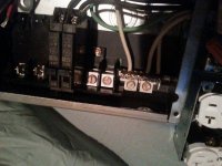
I am in urgent need of advice before I plug this fire hazard in
Here is a little info.
8/3 +Ground from main panel on a 40 amp 240 coming into my sub panel.
Then 4 plugs ran on there own breakers (Ones I had laying around)
Wiring to plugs are 10 AWG at 120 and 20 amp plugs.

I want to hook in a 240 plug eventually and thats why I have the 2 pole 30 amp breaker in there. but for the time being I am not going to use it.

I NEED ALL FEEDBACK PLEASE
Thank you all that take your time to help out with the dark side of electric we dont know


Jhhnn

Active member
Veteran
I am in urgent need of advice before I plug this fire hazard in
Here is a little info.
8/3 +Ground from main panel on a 40 amp 240 coming into my sub panel.
Then 4 plugs ran on there own breakers (Ones I had laying around)
Wiring to plugs are 10 AWG at 120 and 20 amp plugs.

I want to hook in a 240 plug eventually and thats why I have the 2 pole 30 amp breaker in there. but for the time being I am not going to use it.

I NEED ALL FEEDBACK PLEASE
Thank you all that take your time to help out with the dark side of electric we dont know

https://www.icmag.com/ic/picture.php?albumid=66052&pictureid=1571049View Image https://www.icmag.com/ic/picture.php?albumid=66052&pictureid=1571050View Image https://www.icmag.com/ic/picture.php?albumid=66052&pictureid=1571053View Image https://www.icmag.com/ic/picture.php?albumid=66052&pictureid=1571052View Image https://www.icmag.com/ic/picture.php?albumid=66052&pictureid=1571051View Image

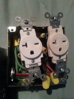
I don't think the ground wiring at the receptacle boxes is technically correct. A better way would be to bring the green to a screw in the raised boss on the box & branch from there to each duplex receptacle. Or use a wire nut & short pigtails to each receptacle. Or you can use bare #12 solid wire looped between the receptacles & back to the breaker panel junction, depend on the receptacle mounting tabs & physical connections to ground the box.

The objective is to have a wire ground from every receptacle to the panel & back to the main box.

Your sub panel must not be grounded to anything except the main panel unless it's in an outbuilding.

When you go to 240v the breaker shouldn't exceed 20A to properly protect the appliance cords.

That's my limited experience, anyway. Rives may see it a little differently & he's the best we have.
 

rives

Inveterate Tinkerer
Mentor
ICMag Donor
Veteran
I don't think the ground wiring at the receptacle boxes is technically correct. A better way would be to bring the green to a screw in the raised boss on the box & branch from there to each duplex receptacle. Or use a wire nut & short pigtails to each receptacle. Or you can use bare #12 solid wire looped between the receptacles & back to the breaker panel junction, depend on the receptacle mounting tabs & physical connections to ground the box.

The objective is to have a wire ground from every receptacle to the panel & back to the main box.

Your sub panel must not be grounded to anything except the main panel unless it's in an outbuilding.

When you go to 240v the breaker shouldn't exceed 20A to properly protect the appliance cords.


Jhhnn is correct - the grounding should go to the box and distribute from there. The idea is that the box and the downstream components all remain grounded even if you have loose (or nonexistent) screws holding the receptacles or the cover in place. Instead, you grounded one receptacle first, jumpering the ground to the second receptacle via the cover plate, and from the second receptacle back to the box. There are any number of ways that the grounding can be compromised this way.

Jhhnn misspoke a bit about the sub grounding - all of the grounding should be intact there and the panel grounded, but the neutral is not grounded at this point. There should be two busses like you have, but the neutral buss has to be isolated from ground buss and the enclosure - the only place that they should be tied together is at the main panel. This is done to eliminate "ground loops", which will raise hell with electronics and make your audio equipment hum at 60 cycles.

#10 wire is way overkill for a 20a circuit unless you have very long distances to run, and it is frequently difficult to fit properly into the receptacles (probably why you used crimp-on terminals). For future reference, either "commercial" or "specification" grade receptacles are much higher quality than conventional receptacles and make far better connections with a clamp plate (you may actually have used them, I can't tell from the pictures. If so, getting those screws out and back into the clamp plate must have been no fun - they are usually designed to be captive screws).
 
Last edited:

Jhhnn

Active member
Veteran
Thanks, rives. When I talked about grounding the sub panel enclosure I meant that it shouldn't be grounded to anything like a cold water pipe or directly mounted to anything like a steel support post set in concrete. Any actual earth ground must be at the main panel.

What many sub panel boxes don't include is a buss bar for the ground wires which needs to be purchased separately. It's extremely useful, actually necessary imho. As you say, grounds & neutrals must not be co-mingled at a sub panel even though they connect to the same place in the main panel.

This is a pic of my sub panel, not finished or mounted showing the separate ground buss bar mounted directly to the enclosure-

https://www.icmag.com/ic/picture.php?albumid=57519&pictureid=1343859

More pics in my albums that I need to update for anybody interested.
 
Thank you

Thank you

I really do appreciate the input and criticism this is my first real electrical project other then audio systems and computer building and I really enjoyed it. I am glad I have the best looking out for me. I am going to take your guys advice work on it tonight and repost some more pictures.
If you guys dont mind, check back tomarrow and let me know if you see any other issues, and if there is anything I can do better, or change, or even ADD :)

THANK YOU AGAIN
 
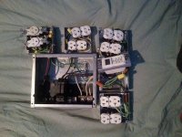
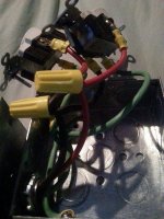
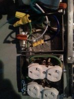
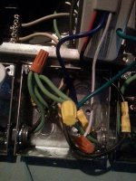
Fixed it up

Fixed it up

Rives Here I am again I need some input,
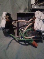
Far starters, I upgraded all wire to 12 as told, Made sure my white wires were not anywhere touching the ground in the panel, took the crimps off and used the terminal on the side of the outlets.

I also bought a timer, and attached it to the bottom right outlet, grounded ALL BOXES and Pig tailed to each outlet. I also bought a 20amp double pole for the top right (Not installed yet) and I bought another 20amp Single Pole for 120.

As far as the top outlet, I used wire nuts for the two hots, is that ok?

and for the Timer, I hooked the timer green to green (Ground) and the Black from the Breaker then the blue to the the hot on the outlet. The white is piggy-tailed to the outlet? Im not sure if you guys need any clearer pictures but could you just look it over and let me know what you think again any feedback, positive, negative, comments suggestions, upgrades, its ALL appreciated.

Love all my fellow ICMAG FRIENDS !! THANK YOU ALL
 

Attachments

  • 12784643_10204255154617853_1535556355_n.jpg
    12784643_10204255154617853_1535556355_n.jpg
    68.8 KB · Views: 27
  • 12784762_10204255155297870_2010260402_n.jpg
    12784762_10204255155297870_2010260402_n.jpg
    71.6 KB · Views: 25
  • 12804307_10204255153937836_1792923272_n.jpg
    12804307_10204255153937836_1792923272_n.jpg
    81.1 KB · Views: 24
  • 12804420_10204255154897860_333772893_n.jpg
    12804420_10204255154897860_333772893_n.jpg
    71.4 KB · Views: 22
  • 12822261_10204255156617903_614584749_n.jpg
    12822261_10204255156617903_614584749_n.jpg
    72 KB · Views: 23
  • 12834446_10204255157017913_2055495044_n.jpg
    12834446_10204255157017913_2055495044_n.jpg
    68.5 KB · Views: 24
  • 12834825_10204255155417873_1929630785_n.jpg
    12834825_10204255155417873_1929630785_n.jpg
    72.8 KB · Views: 26

rives

Inveterate Tinkerer
Mentor
ICMag Donor
Veteran
A couple of things: I don't know what you are planning on driving with the timer, but be aware that most timers aren't capable of driving even medium-wattage ballasts reliably - you may need to drive a power relay with the timer, and then your ultimate load.

The ground terminal on the receptacles lack a clamp plate, and don't lend themselves well for use with stranded wire. Over time the wire may try and squirt out from under the head of the screw. I usually keep some scrap uninsulated, solid wire from Romex around for the grounding, or the wire can be tinned with solder to make it similar to solid wire. Crimp-on terminals can be used, but again, the screws are usually a captive design and can be difficult to use with ring terminals. Fork terminals would be an option, but I prefer rings for any ground connection.

It looks like the orange wire nuts are way over capacity in some places. They usually have a maximum capacity of (2) #14 wires.

Pigtailing the hot wires so that they can be paralleled to the receptacles is fine.

The timer wiring sounds like it is probably right, but there are many different configurations and color codes used, and I would need to see the schematic to be sure. The neutral connection should be fine in parallel - they will not be switching the neutral.
 
Rives

Rives

Hello everyone AGAIN lol

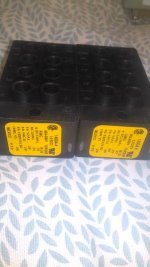
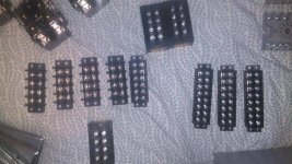
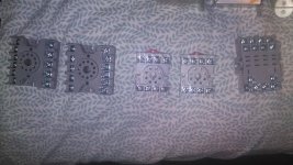
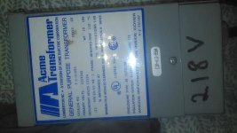
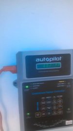
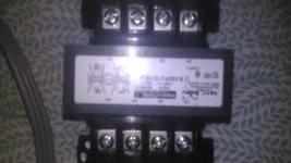
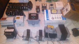
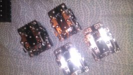
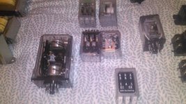
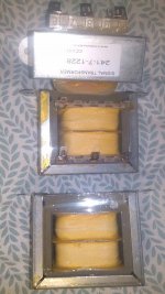
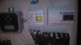
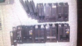
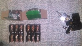
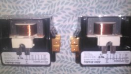
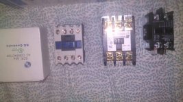
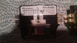
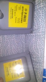
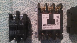
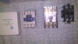
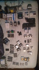
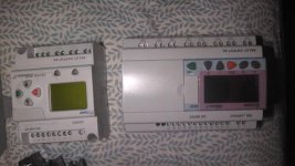
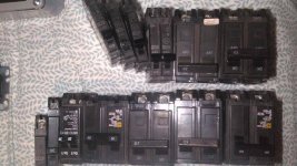
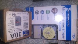
So, I ran into a craigslist add of electrical parts and I ended up picking up the whole box of stuff for $100 now the problem is what to do with it? I know a few different things, but I need diagrams, or suggestions or something COOL lol. and obviously my home made box, and the auto pilot didnt come with it, I made and bought those separate, but would love to incorporate them (THE PLCS DID hence why I bought it). I Have plenty of outlets, boxes, etc etc. what to do what to do?

Give me ideas, let me know what you think!!

Specially you Rives!!
 

Attachments

  • IMG_20160315_192227.jpg
    IMG_20160315_192227.jpg
    42.9 KB · Views: 25
  • IMG_20160315_192203.jpg
    IMG_20160315_192203.jpg
    58.6 KB · Views: 23
  • IMG_20160315_192145.jpg
    IMG_20160315_192145.jpg
    52.7 KB · Views: 27
  • IMG_20160315_192131.jpg
    IMG_20160315_192131.jpg
    39.2 KB · Views: 27
  • IMG_20160315_192038.jpg
    IMG_20160315_192038.jpg
    21.9 KB · Views: 25
  • IMG_20160315_192340.jpg
    IMG_20160315_192340.jpg
    28.5 KB · Views: 25
  • IMG_20160315_192329.jpg
    IMG_20160315_192329.jpg
    55.4 KB · Views: 24
  • IMG_20160315_192310.jpg
    IMG_20160315_192310.jpg
    43.6 KB · Views: 28
  • IMG_20160315_192301.jpg
    IMG_20160315_192301.jpg
    53.3 KB · Views: 27
  • IMG_20160315_192245.jpg
    IMG_20160315_192245.jpg
    51.2 KB · Views: 24
MORE..
 

Attachments

  • IMG_20160315_192349.jpg
    IMG_20160315_192349.jpg
    37.8 KB · Views: 27
  • IMG_20160315_192354.jpg
    IMG_20160315_192354.jpg
    51.3 KB · Views: 26
  • IMG_20160315_192401.jpg
    IMG_20160315_192401.jpg
    52.9 KB · Views: 28
  • IMG_20160315_192413.jpg
    IMG_20160315_192413.jpg
    32.1 KB · Views: 24
  • IMG_20160315_192425.jpg
    IMG_20160315_192425.jpg
    45.2 KB · Views: 28
  • IMG_20160315_192620.jpg
    IMG_20160315_192620.jpg
    41.8 KB · Views: 27
  • IMG_20160315_192437.jpg
    IMG_20160315_192437.jpg
    47.6 KB · Views: 23
  • IMG_20160315_192452.jpg
    IMG_20160315_192452.jpg
    37 KB · Views: 27
  • IMG_20160315_192602.jpg
    IMG_20160315_192602.jpg
    51.1 KB · Views: 25
AND MORE. PLEASE HELP :)
 

Attachments

  • IMG_20160315_192425.jpg
    IMG_20160315_192425.jpg
    45.2 KB · Views: 26
  • IMG_20160315_192709.jpg
    IMG_20160315_192709.jpg
    63.8 KB · Views: 27
  • IMG_20160315_192639.jpg
    IMG_20160315_192639.jpg
    41.6 KB · Views: 25
  • IMG_20160315_192633.jpg
    IMG_20160315_192633.jpg
    56.3 KB · Views: 25
  • IMG_20160315_192431.jpg
    IMG_20160315_192431.jpg
    43.1 KB · Views: 24

rives

Inveterate Tinkerer
Mentor
ICMag Donor
Veteran
I'm not sure where to point you here, it's a bit like having a garage full of parts and trying to figure out if you want to build a car or a chainsaw. It looks like you got a hell of a deal, but the PLC/programmable relays take a substantial amount of effort to learn how to program and, and the skill is perishable if you don't work with them frequently. The greenhouse controller may be a bit more user friendly. There are a ton of great parts there, but you will need to decide what direction you want to head and how much effort you are willing to invest.
 
I am willing to invest what ever amount of money time effort it takes, I want to make my own 4k LED Grow set up on timers, pretty much what im saying is I want a whole room controller, Humidity, Temp, etc etc.. all on 1 board. as of right now i started by running 6/4 from my main box on a 60 amp breaker. I just honestly dont know where to start.

If you want make me a list of parts, to a cool controller and make me a diagram with a good amount of detail and I will western union you some money before hand even or if you have another way. I have read enough posts to know that your one of the only people I trust on here when it comes to electrical and it would be a pleasure to have a controller designed by you. You make the controller to your specifications, and I will copy it.

:) PLEASE lol.
 
give me the price to make a nice planned out detailed design, down to wire size and color with the flow and etc. 50? 100? whats it going to take.
 

rives

Inveterate Tinkerer
Mentor
ICMag Donor
Veteran
The first thing is to find out if your controllers are capable of analog control if you want to do humidity, temperature, etc. The vast majority are digital only and can't interface with an analog signal. They could still be used, but rather than doing the control in them (which can be a MUCH more involved process than straight digital control) you could interface to dedicated modules that controlled that portion of the process. It could potentially be much cheaper, too - analog gear can be very spendy, whereas thermostats and humidistats are pretty cheap.....

Get the nameplate information on each of the controllers and we can track down what they are capable of and what programming tools are needed. Some vendors give the programming software away and charge a nominal fee for the interface cable, and some vendors bend you over for the gear. Some controllers have relay outputs, where others use transistors, triacs, etc, etc.
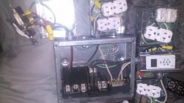
Pictured below is the controller that I built for myself. It is a straight-digital control Allan-Bradley. The yellow wires are inputs, the light blue wires are outputs that drive the external relays to bump up the current capacity and protect the controller, and there are breakers for the controller power, the control outputs, the relays, the ballasts, and one with a shunt trip for use with a smoke detector on the air handling system. There is several hundred dollars there without the cost of the controller.

Incidentally, I don't recall anyone actually completing a project like this that didn't have a programming or electrical background.

picture.php
 

rives

Inveterate Tinkerer
Mentor
ICMag Donor
Veteran
I can follow most of what is discussed in this thread... But this stuff is going way over my head

That is the point of my last statement - for someone without a background in the industry, it's a hell of a big task to undertake.
 
Rives would you be interested in making a secure, payment option IE Paypal etc, making one and sending it to me? I wouldn't mind putting the money up first if you were to make me something along the lines of that and obviously you put your profit amount in with the parts amount. you would let me know the cost.
 
Top