
-
ICMag with help from Landrace Warden and The Vault is running a NEW contest in November! You can check it here. Prizes are seeds & forum premium access. Come join in!
You are using an out of date browser. It may not display this or other websites correctly.
You should upgrade or use an alternative browser.
You should upgrade or use an alternative browser.
3-in-1 Dimming including On/Off function for meanwell drivers
- Thread starter AvidLerner
- Start date
AvidLerner
Member
How about four channels with IR and a remote control http://www.ebay.com/itm/4-Channel-5...26d369a&pid=100005&rk=6&rkt=6&sd=152191861657
peace
Avid
peace
Avid
AvidLerner
Member
there are plenty of options available. that is the purpose of DIY. peace. Everyone's needs are unique. if you want blue tooth or even IR you cna get it from ebay direct. peace
Avid
Avid
AvidLerner
Member
Here is a relay that will come on when the soil is dry and turn on a water pump. http://www.ebay.com/itm/Soil-Humidi...894429?hash=item4d3bde1edd:g:YbYAAOxyUrZSoZi1
peace
Avid
peace
Avid
I wouldn't use those sensors in that relay configuration. it will for sure overwater the plants. Also, those probes are sensitive to corrosion and will become useless in months, causing more overwatering after some time passes, and continouss overwatering when they go out cause of corrosion.
I used that kind of sensors to water plants, but with the help of an arduino uno and extensive code including lots of software and hardware fail-safes. It will work, but you still need to change probes every 3-6 months for good results.
I used that kind of sensors to water plants, but with the help of an arduino uno and extensive code including lots of software and hardware fail-safes. It will work, but you still need to change probes every 3-6 months for good results.
AvidLerner
Member
I wouldn't use those sensors in that relay configuration. it will for sure overwater the plants. Also, those probes are sensitive to corrosion and will become useless in months, causing more overwatering after some time passes, and continouss overwatering when they go out cause of corrosion.
I used that kind of sensors to water plants, but with the help of an arduino uno and extensive code including lots of software and hardware fail-safes. It will work, but you still need to change probes every 3-6 months for good results.
There are better sensors like these http://www.vegetronix.com/Products/VH400/ that you can use with the relay system. vegatronics is he best sensors, at about $40 each for soil moisture and temperature sensors that can be hooked to these relays. people arfe looking for automation solutions and i see plenty and share them. Cheap sensors, but free of any computer other than the range set up on the board.
Decided to go analog first and complicate the hobby later.
Would this be a good pot for 1-10v dimming of a hlg driver?
http://www.mouser.com/ProductDetail...VpH/0VKOBg==&gclid=CIf3q4T21c8CFVdahgodcWgGDA
And what's the difference with the ohm value? I've heard 100k for one driver, and 50 and lower for more drivers?
Thanks in advance.
Would this be a good pot for 1-10v dimming of a hlg driver?
http://www.mouser.com/ProductDetail...VpH/0VKOBg==&gclid=CIf3q4T21c8CFVdahgodcWgGDA
And what's the difference with the ohm value? I've heard 100k for one driver, and 50 and lower for more drivers?
Thanks in advance.
AvidLerner
Member
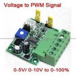
I got a couple of these in today and tested them with Meanwell led drivers, and they work great. You need either a 9v battery or a 10v power supply, pick one. Both tested well. This device allows both a 5v pwm signal and a 10v pwm signal. These are made for cnc machines running with pc's using 5v signals, while motors need 10v to go fast.
http://www.ebay.com/itm/PWM-0-10V-D...3813&clkid=8910451012931607078&_qi=RTM2247625
peace
Avid
http://www.ebay.com/itm/PWM-0-10V-D...3813&clkid=8910451012931607078&_qi=RTM2247625
peace
Avid
AvidLerner
Member
Decided to go analog first and complicate the hobby later.
Would this be a good pot for 1-10v dimming of a hlg driver?
http://www.mouser.com/ProductDetail...VpH/0VKOBg==&gclid=CIf3q4T21c8CFVdahgodcWgGDA
And what's the difference with the ohm value? I've heard 100k for one driver, and 50 and lower for more drivers?
Thanks in advance.
yes. should work great. don;'t forget to get a 100k resistor to put before one leg of the pot. If you use on pot for more than one driver you decrease by 50% to a 50k pot and so on. four max. peace
Avid
AvidLerner
Member
A couple of updates:
1. Dimming capability. thee are a number of opportunities for 3in1 dimming. For the DIY person there is a few of what has been posted here. Most are what are called "High Side" dimming. if you google that term you will find many opportunities to build a dimming circuit. However if you are not so inclined to soldering and transistors, resistors, capacitors, etc, you m ight be interested in a pcb board already built for PLC or industrial controls and automation. Arduino's are being use used in much PLC now. Here is the link for the pwm driver. they range from $3 to $7 each channel. http://www.ebay.com/itm/291855581114?_trksid=p2057872.m2749.l2649&ssPageName=STRK:MEBIDX:IT
2. Timers. Each light fixture needs to be timed for either 12/12, 18/6, 20/4, 3o min at lights out, etc. Each of those schedules requires timers. If you add up the costs of the timers to control each fixture, $30-50 each, the cost goes up quickly. Replacing all of those timers, 8-16 is a change event. never worrying about timers being on schedule or breaking down and requiring replacement, while it stayed on, when the rest of the lights went off. SAD face. I developed the GrowGreen Controller with this the top priority. When you consider the cost of 8 timers at even $20 each $160, is still more than one GrowGreen Controller alone. Dimming becomes the bonus.
3. I have shared all of the circuits I have developed for dimming Meanwell drivers and they all work, as well as those alluded to b y others. In order to build them you need the tools and components, ergo the board available on ebay for $5. Another approach is to use a optocoupler or light emitting diode and a light accepting diode to transfer signal from the 5v Arduino to the 10v Meanwell driver. A number of optocouplers are available for this purpose. You will need a 1k resistor on the pwn pin to the diode, and another 1k resistor, to create the high side switch, between 12v power and the Collector of the transistor, tying the emitter of the transistor to ground. The leads from the two ends of the 1k resistor go to the Meanwell driver. Positive from the power supply goes to the Dim+ and the Collector side of the resistor goes to Dim-, creating a 0-10v circuit driven by the Arduino 5v pwm signal. BTW, if you tap the signal coming out of the Arduino pin and ground, yopu also have a 5v pwm signal to use for on/off functionality of the Meanwell driver, while still having the ability to dim the drivers as well. Available optocouplers are the CYN75B, CYN75GB, 4N25, to name a few available.
4. If you also use supplemental lighting, Far Red, Deep Red, IR, or royal or all the above, you can also control these with an LDD driver board, 4up or 6up from rapid leds, coralux or ebay. you can build them yourself or buy them built, and populate them with various LDD drivers, 800ma, 1000ma, etc. for each supplemental light used. Each of these LDD drivers can also be controlled to dim, or on/off with just a 5v pwm signal. Any LEd controller can do that, but only the GrowGreen controller has 8 channels and flexible control over each channel independent of other channels.
Attachments
Last edited by a moderator:
Decided to go analog first and complicate the hobby later.
Would this be a good pot for 1-10v dimming of a hlg driver?
http://www.mouser.com/ProductDetail...VpH/0VKOBg==&gclid=CIf3q4T21c8CFVdahgodcWgGDA
And what's the difference with the ohm value? I've heard 100k for one driver, and 50 and lower for more drivers?
Thanks in advance.
http://www.ebay.com/itm/301361465591?_trksid=p2057872.m2749.l2649&ssPageName=STRK:MEBIDX:IT
I got these and they work great. The angled connection points made them very easy to mount in a project box. And they do actually have a 6mm dia. post.
I skipped the resistor. My light maintains 10% output with the pots turned down to 0.
AvidLerner
Member
Creating a COB fixture with supplemental lighting comparable to the commercial fixtures available on the market today has been my focus from the start. I wanted a DIY light that surpassed mars and others with supplemental led diodes, creating a complete light spectrum. I wanted what is sold, without having to buy one. I bought a commercial light a diamond and realized I could build a better fixture for less, but I would need an led controller to create the same result.
I have been able to build that COB fixture with Deep Red, InfraRed, Far Red, and Royal Blue with two 200w COB drivers using six channels. I can add two more COB fixtures if I desire and have a total of 800w of COB's, four fixtures covering a 4x4 space. Schedule control over all light spectrum is why an eight channel pwm driven arduino uno based system. I did not place my supplemental leds in a circular pattern, I used bar stock heat sinks attached to the main active cooling heat sinks, creating a complete color rendition environment maximizing growth potential with color corrected lighting.
I have read many grow journals for a 4x4 grow. Replacing the timers controlling four COB fixtures alone costs $200. More importantly, having peace of mind that no timer will fail, or change time, or require replacement over time, is reassuring. Dimming COB fixtures is a secondary issue for me, as most COB lights are designed to be on 100% . The led controller lights each fixture one after another instead all on at once reducing inrush current issues for the grow site.
This is why I built the eight channel version. The six channel version can support a smaller grow of a 3x3 or a 2x4 grow. I wanted peace of mind. I have that now. I want others to have that same piece of mind so growers can focus on what they do best create and grow great genetics. That is why there is a DIY version, which I support fully, just as if you bought a GrowGreen from me, I support you and help you get the controller up and running the way you want it to run. Just as important, the code is in the public domain allowing for even more changes to come from the community
I did not start this to create a sell-able product, I started this to fill a void that I feel is needed for the DIY community to create a quality lighting environment, led lighting control's. peace
AvidLerner
Member
http://www.ebay.com/itm/301361465591?_trksid=p2057872.m2749.l2649&ssPageName=STRK:MEBIDX:IT
I got these and they work great. The angled connection points made them very easy to mount in a project box. And they do actually have a 6mm dia. post.
I skipped the resistor. My light maintains 10% output with the pots turned down to 0.
You might want to use a resistor, as at 10% is not recommended by Meanwell. a 100k resistor may save you some money. peace
AvidLerner
Member
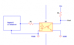
Here is a basic "high side switch" optocoupler circuit. On the left side is the arduino 5v pwm pin input, on the right is the Meanwell 01v pwm signal U1 is a optocoupler CNY75GB, R1and R2 are 1k ohms, Vcc is 10v or a 9v battery. GND is Ground from the Ardiino and the Meanwell driver. Output is 0-10v pwm signal and input is 5v pwm signal. Hope this helps folks understaand a high side switch circuit. example circuit from a manufacturerhttp://www.vishay.com/docs/83741/83741.pdf
Attachments
AvidLerner
Member
yes. You can use a 12c battery too and it works. I just have 9v batteries laying around and 12v are harder to find in my neighborhood. I use 9v for testing. you only get about 80% of the volts on a high side switch. I recommend using a 12v power supply for best results. batteries do wear out in time, and the only way you would know your battery is wearing out is when you don't get no stinking dimming. lol, or else do the touch to the tongue test. I like that one more. mmmm. peace
Avid
Avid
AvidLerner
Member
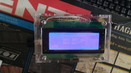
A little update on things. Here is a picture of the new controller case, clear. and I have developed some code that runs automation using IoT and a raspberry Pi3, check it out.. here are some screen shots to make you drool.
Attachments


AvidLerner
Member
A little update on dimming. I have been working on another led controller project for anotehr client that wants the brightest dimmer possible. So I did some more research and came up with the best dimmer available and simple too. The dimmer circuit consists of a the pwm pin from arduino tied to the 2.2k resistor, the 2.2K resistor tied to the base of the TIP 120 MOSFET, the Collector of the MOSFET is tied to the DIM- and the Emitter of the MOSFET is tied to the DIM+ of the Meanwell drier. that is it. simple but effective
The post is way old I'm new to electronics but have the passion for growing and now wants to start indoor. I want to control my light with the DIY as i like it much more, the thing i tried to read over and over the posts and couldn't figure out the schematic all the components and how to get the PWM control channels. Anyone would help? Avid are you still active?

