AvidLerner
Member
I participate at other sites and I love tinkering with electronics. I have been following a discussion on 3 in 1 Dimming capabilities and what it is useful for.
For me, I found out how to use an arduino device; Storm, Typhon, or arduino uno; to dim led fixtures identical to the ones we DIY here with meanwell HLG series of dimmable drivers.
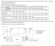
The article talks about many features, but there is an entire article elsewhere about not only dimming but also turning on/off HLG series of drivers already available in Europe, but not in the USA.
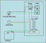
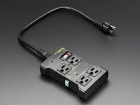
The figure at the bottom shows an on/off device. The device is available in two formats, hobby build or assembled. The hobby version can be found by searching for controllable power outlet on sparkfun
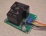
SparkFun Beefcake Relay Control Kit
SparkFun Beefcake Relay Control Kit
KIT-11042 RoHS Open Source Hardware
16
Description: Your 5 volt system can wield great power with this big beefy relay board. How does 20 amps at 220VAC sound? The SparkFun Beefcake Relay Control Kit contains all the parts you need to get your high-power load under control.
The heart of the board is a sealed, SPDT-NO 20A Relay. The relay is controlled by 5V logic through a transistor and an LED tells you when the relay is closed. This is a kit, so it comes as through-hole parts with assembly required which makes for some nice soldering practice. Screw terminal connectors on either side of the board make it easy to incorporate into your project.
Note: There are some pretty beefy traces connecting the relay to the load pins, but the 2-pin terminals are only rated for 8A max! If you plan on connecting a larger load you’ll need to solder directly to the board. As always with high current and voltage, play it safe and use your judgment when deciding how much of a load you want to put on a board.
Note: Although we have revised this PCB to provide better isolation for the high voltage traces, this board is really meant for someone with some experience. If you’re uncomfortable soldering or dealing with high voltage, please checkout the PowerSwitch Tail II. The PowerSwitch Tail II is fully enclosed making it a lot safer.
Documents:
Schematic
Eagle Files
Datasheet (JQX-15F/005-1Z1)
Relay Tutorial
Parts Wishlist
GitHub
Product Video
or by looking for the same at yourduino
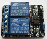
Opto-Isolated 2 Channel Relay Board
SKU: EA-040407
Original Price: $6.50
Sale Price: $3.00
Vol. Pricing:
Quantity: 50+ 100+ 500+
Price: $2.70 $2.40 $2.25
Stock: 246
Quantity:
Opto-Isolated 2 Channel Relay Board (We have sold thousands, now get a good price!)
Please note: Large Quantities may have a longer lead time. Please email for details: [email protected].
See more details, applications on our WIKI here:
With high-current relays, AC250V 10A ; DC30V 10A NOTE: Each relay draws about .08A (80ma) so about 4 relays are the maximum you should run from the Arduino +5V supply. (Running from USB it may be less). More than 2 relays: we recommend you use a separate 5V supply for the relays.
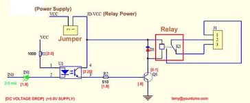
NOTES: If you want complete optical isolation, connect "Vcc" to Arduino +5 volts but do NOT connect Arduino Ground. Remove the Vcc to JD-Vcc jumper. Connect a separate +5 supply to "JD-Vcc" and board Gnd. This will supply power to the transistor drivers and relay coils.
If relay isolation is enough for your application, connect Arduino +5 and Gnd, and leave Vcc to JD-Vcc jumper in place.
NOTE: It is sometimes possible to use these relay boards with 3.3V signals, IF the JD-VCC(RelayPower) is provided from a +5V supply and the VCC to JD-VCC jumper is removed. . That 5V relay supply could be totally isolated from the 3.3V device, or have a common ground IF opto-isolation is not needed. If used with isolated 3.3V signals, VCC (To the input of the opto-isolator, next to the IN pins) should be connected to the 3.3V device's +3.3V supply. NOTE: Some RaspberryPi users have found that some relays are reliable and others do not actuate sometimes. It may be necessary to change the value of R1 from 1000 ohms to something like 220 ohms, or supply +5V to the VCC connection.
NOTE: The digital inputs from Arduino are Active LOW: The relay actuates and an LED lights whe the input pin is LOW, and turns off on HIGH. See the Wiki article for how-to assure relays do not activate at power-on time.
Schematic Diagram: see attachments
Please Read This Electrical Safety / Disclaimer page before using the relay board in this product.
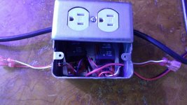
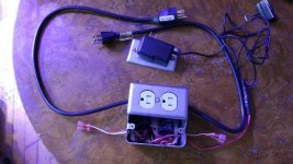
I bought the kit and assembled it and tested it today with my coralux storm controller and it works. Next I will build a duplex outlet box with two power controllers on the outside to cotnrol turning lights on/off, dim, and dim Far Red, Deep Red, IR, and Royal Blue, all controlled from one console for two rooms.
I hope this helps others and they can learn from this, as well
peace
AL
Attachments
Last edited:

