What's new
  • ICMag and The Vault are running a NEW contest in October! You can check it here. Prizes are seeds & forum premium access. Come join in!

3-in-1 Dimming including On/Off function for meanwell drivers

I participate at other sites and I love tinkering with electronics. I have been following a discussion on 3 in 1 Dimming capabilities and what it is useful for.

For me, I found out how to use an arduino device; Storm, Typhon, or arduino uno; to dim led fixtures identical to the ones we DIY here with meanwell HLG series of dimmable drivers.

The article talks about many features, but there is an entire article elsewhere about not only dimming but also turning on/off HLG series of drivers already available in Europe, but not in the USA.

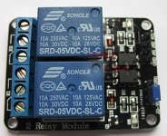
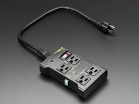
The figure at the bottom shows an on/off device. The device is available in two formats, hobby build or assembled. The hobby version can be found by searching for controllable power outlet on sparkfun
SparkFun Beefcake Relay Control Kit

SparkFun Beefcake Relay Control Kit
KIT-11042 RoHS Open Source Hardware
16

Description: Your 5 volt system can wield great power with this big beefy relay board. How does 20 amps at 220VAC sound? The SparkFun Beefcake Relay Control Kit contains all the parts you need to get your high-power load under control.

The heart of the board is a sealed, SPDT-NO 20A Relay. The relay is controlled by 5V logic through a transistor and an LED tells you when the relay is closed. This is a kit, so it comes as through-hole parts with assembly required which makes for some nice soldering practice. Screw terminal connectors on either side of the board make it easy to incorporate into your project.

Note: There are some pretty beefy traces connecting the relay to the load pins, but the 2-pin terminals are only rated for 8A max! If you plan on connecting a larger load you’ll need to solder directly to the board. As always with high current and voltage, play it safe and use your judgment when deciding how much of a load you want to put on a board.

Note: Although we have revised this PCB to provide better isolation for the high voltage traces, this board is really meant for someone with some experience. If you’re uncomfortable soldering or dealing with high voltage, please checkout the PowerSwitch Tail II. The PowerSwitch Tail II is fully enclosed making it a lot safer.

Documents:

Schematic
Eagle Files
Datasheet (JQX-15F/005-1Z1)
Relay Tutorial
Parts Wishlist
GitHub
Product Video

or by looking for the same at yourduino

Opto-Isolated 2 Channel Relay Board
SKU: EA-040407
Original Price: $6.50
Sale Price: $3.00
Vol. Pricing:
Quantity: 50+ 100+ 500+
Price: $2.70 $2.40 $2.25
Stock: 246
Quantity:
Opto-Isolated 2 Channel Relay Board (We have sold thousands, now get a good price!)

Please note: Large Quantities may have a longer lead time. Please email for details: [email protected].

See more details, applications on our WIKI here:

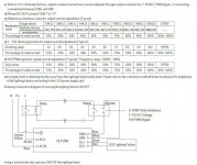
With high-current relays, AC250V 10A ; DC30V 10A NOTE: Each relay draws about .08A (80ma) so about 4 relays are the maximum you should run from the Arduino +5V supply. (Running from USB it may be less). More than 2 relays: we recommend you use a separate 5V supply for the relays.

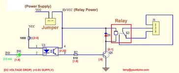
NOTES: If you want complete optical isolation, connect "Vcc" to Arduino +5 volts but do NOT connect Arduino Ground. Remove the Vcc to JD-Vcc jumper. Connect a separate +5 supply to "JD-Vcc" and board Gnd. This will supply power to the transistor drivers and relay coils.

If relay isolation is enough for your application, connect Arduino +5 and Gnd, and leave Vcc to JD-Vcc jumper in place.

NOTE: It is sometimes possible to use these relay boards with 3.3V signals, IF the JD-VCC(RelayPower) is provided from a +5V supply and the VCC to JD-VCC jumper is removed. . That 5V relay supply could be totally isolated from the 3.3V device, or have a common ground IF opto-isolation is not needed. If used with isolated 3.3V signals, VCC (To the input of the opto-isolator, next to the IN pins) should be connected to the 3.3V device's +3.3V supply. NOTE: Some RaspberryPi users have found that some relays are reliable and others do not actuate sometimes. It may be necessary to change the value of R1 from 1000 ohms to something like 220 ohms, or supply +5V to the VCC connection.

NOTE: The digital inputs from Arduino are Active LOW: The relay actuates and an LED lights whe the input pin is LOW, and turns off on HIGH. See the Wiki article for how-to assure relays do not activate at power-on time.

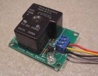
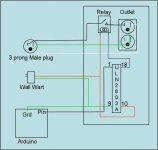
Schematic Diagram: see attachments

Please Read This Electrical Safety / Disclaimer page before using the relay board in this product.


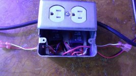
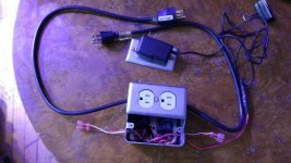
I bought the kit and assembled it and tested it today with my coralux storm controller and it works. Next I will build a duplex outlet box with two power controllers on the outside to cotnrol turning lights on/off, dim, and dim Far Red, Deep Red, IR, and Royal Blue, all controlled from one console for two rooms.

I hope this helps others and they can learn from this, as well
peace
AL
 

Attachments

  • 3in1dimfun1.jpg
    3in1dimfun1.jpg
    75.1 KB · Views: 41
  • large_218_2-relay-isolated-1.jpg
    large_218_2-relay-isolated-1.jpg
    31.2 KB · Views: 34
  • Outlet-1-L.jpg
    Outlet-1-L.jpg
    58.3 KB · Views: 40
  • OptoRelayChannelData-575.jpg
    OptoRelayChannelData-575.jpg
    15 KB · Views: 44
  • arduinopowercontroller.jpg
    arduinopowercontroller.jpg
    21.2 KB · Views: 45
Last edited:
Finished the project. built the two relays, tested the circuits, and I now have a control for two LED light fixtures that draw less than 2 amps and 200 watts each on separate circuits. peace
 

Attachments

  • 20160529_165754_resized.jpg
    20160529_165754_resized.jpg
    45.8 KB · Views: 30
  • 20160529_165815_resized.jpg
    20160529_165815_resized.jpg
    51.6 KB · Views: 27
I will be more than happy to help the DIY folks. I am working on an arduino uno with growers code for controlling multiple lights, tracking temps, running fans that I will make available to the DIY folks, along with even doing some DIY kits for the DIY LED light folks and the rest too. For larger draw lights a larger relay will be needed to handle larger amp draws. There are larger relays out there that do the same. If you buy the relays already built it is a pierce of cake to get two enclosures, one forthe elays and another for the reeceptacles. They recommedn GFCI, but my unit is p[lugged into a GFCI for each light on separate circuits to not drqaw too many amps on one breaker. flexibility is the key peace
 

jikko77

Active member
i've got some semple code, from other project and library.
it's based on dht11 and dht22.
let me know if it may help.

:tiphat:
 
i've got some semple code, from other project and library.
it's based on dht11 and dht22.
let me know if it may help.

:tiphat:

thanks. I will let you know. I am working on a menu system and plan on using a rotary encoder with a push button, easiest to navigate. peace.
 
SO I have narrowed down my choices. I found this unit at adafruit for controlling circuits and it is tested and has a warranty. ->https://www.adafruit.com/products/2935
I am now working on the code for the arduino to power and control the lights and timers, with four to six pwm outputs to control receptacles like this one and led lights directly.

I am working on a grow room controller similar to the Coralux controller for aquariums, but not modified for grow rooms, but totally re-worked and designed with our needs in mind, alone.

I have settled on an lcd shield that has a rotary encoder and can use a menu system. Once i finish the code portion, I will make it available as open source. Considering a DIY kit for DIY lights, a controller, two receptacles, and two extension connectors for light dimming and on/off functionality along with an arduino controller with start/stop timing, and recycle timing to replace all timers in a the grow room. peace
 
I have started using the Adafruit outlet controller, along with a typhon reef controller for testing, while I develop the open source code. I have selected an arduino mega2560 for the foundation, along with and lc shield that has a rotary encoder and a RTC circuit. The outlet controller seems to have no inrush current issues, and starts and stops without hesitation. I can hear the circuit energizing, and I am stoked with that part. leds ramp up and down instead of just on/off. i like that too.

I have developed the menu and I am now working on the code portion. the menu will have a setup, channels, timers, and off functionality at the top level. setup will alow six channels for PWM control, two recycle timer circuits, and independent on/off times for each channel and timer.

The pieces are coming together. I am also looking at the larger operation that has multiple fixtures needing multiple controllers, as well being daisy-chained together for total grow room control. peace
 

jikko77

Active member
sent what i've.
is a mix from different source.
i guess one bit of code was write for rpi, but can be used as well on arduino, with a very little adjust.

keep up the good work man!
 
I have been working with the Arduino Uno and I am using an i2c rgb shield from adafruit that only requires two analog pins to drive the lcd and the five switches. I am also using the dht11 temp and humidity sensor in concert, while maintaining all PWM channels for use. Next is the RTC circuit hookup, awaiting batteries. Once I get the last component, I can focus on final programming. I see the Uno in a project box, with an lcd mounted on the front of it, and outlets for PWM and temperature and humidity sensor connections. I have considered CO2, but I do not use it now. I have cylinder and unit, just not a sensor set to test, expensive, out of my league. Perhaps the experts can provide that code snippet and discus how to connect the unit on an analog pin or two. peace.
 
Here is a sketch i developed to read and post the temp and humidty on the lcd. I am using an i2c adafruit lcd shield.
#define DHT11_PIN 0 // ADC0 Analog pin A0
// include the library code:
#include <Wire.h>
#include <Adafruit_RGBLCDShield.h>
#include <utility/Adafruit_MCP23017.h>


// The shield uses the I2C SCL and SDA pins. On classic Arduinos
// this is Analog 4 and 5 so you can't use those for analogRead() anymore
// However, you can connect other I2C sensors to the I2C bus and share
// the I2C bus.
Adafruit_RGBLCDShield lcd = Adafruit_RGBLCDShield();

// These #defines make it easy to set the backlight color
#define RED 0x1
int LCD_C=16;
int LCD_R=2;
int dhtTemp=0;
int dhtHumidity=0;

// end of i2c rgb lcd shield definitions

void setup()
{
DHTSetup();
SPrintBegin();
PrintBegin();
PrintTempMenu();
} // end setup

void loop()
{
GetDHTData();
PrintTempMenu();

} // end loop

// ---Functions----//
// setup ddrc and portc
void DHTSetup(){
DDRC |= _BV(DHT11_PIN);
PORTC |= _BV(DHT11_PIN);
}
// read dht11 data line for input
byte read_dht11_dat()
{

byte i = 0;
byte result=0;
for(i=0; i< 8; i++)
{
while(!(PINC & _BV(DHT11_PIN))); // wait for 50us
delayMicroseconds(30);
if(PINC & _BV(DHT11_PIN))
result |=(1<<(7-i));
while((PINC & _BV(DHT11_PIN))); // wait '1' finish
}
return result;
}
// serial printbegin
void SPrintBegin()
{
Serial.begin(9600);
Serial.println("Ready");
}
// print setup routine
void PrintBegin()
{
lcd.begin(LCD_C, LCD_R);
lcd.clear();
lcd.setCursor(0,0);
} // end PrintBegin
// print temperature menu on line 1 on lcd
void PrintTempMenu()
{
lcd.setCursor(0,0);
lcd.print("Temp: F/RH: %");
lcd.setCursor(5,0);
lcd.print(dhtTemp);
lcd.setCursor(13,0);
lcd.print(dhtHumidity);
lcd.setCursor(15,0);
lcd.print("%");
}
// read data for input from dht11 temp/humidity sensor
void GetDHTData()
{
byte dht11_dat[5];
byte dht11_in;
byte i;// start condition
// 1. pull-down i/o pin from 18ms
PORTC &= ~_BV(DHT11_PIN);
delay(18);
PORTC |= _BV(DHT11_PIN);
delayMicroseconds(40);
DDRC &= ~_BV(DHT11_PIN);
delayMicroseconds(40);

dht11_in = PINC & _BV(DHT11_PIN);
if(dht11_in)
{
Serial.println("dht11 start condition 1 not met");
lcd.print("DHT11 checksum error");
return;
}
delayMicroseconds(80);
dht11_in = PINC & _BV(DHT11_PIN);
if(!dht11_in)
{
Serial.println("dht11 start condition 2 not met");
return;
}

delayMicroseconds(80);// now ready for data reception
for (i=0; i<5; i++)
dht11_dat = read_dht11_dat();
DDRC |= _BV(DHT11_PIN);
PORTC |= _BV(DHT11_PIN);
byte dht11_check_sum = dht11_dat[0]+dht11_dat[1]+dht11_dat[2]+dht11_dat[3];// check check_sum
if(dht11_dat[4]!= dht11_check_sum)

{
Serial.println("DHT11 checksum error");
}
dhtTemp=(int)round(1.8*dht11_dat[2]+32);
dhtHumidity=(int) dht11_dat[0];
} // end read data
---
peace
Avid
 

exploziv

pure dynamite
Administrator
Veteran
Get a RTC in there man, it will be easier to control lights and log things, and it will keep memory if iy has a backup battery, so your controller will know what to do even after a restart. And don't get a cheap one, they are quite bad at keeping time. Around 5 usd you should find great models on ebay. A bit more if using dedicated electronic parts sites.

Also, I would move this part from the loop to the setup:

lcd.setCursor(0,0);
lcd.print("Temp: F/RH: %");

It will take less time to go through the loop, and make it easier for the microprocessor. Also there is some error in there where you overwrite the values over the text that is printed by the command above. To fix that just add spaces to the text when printing it, then just move the values printing to the spaces you created. Before you write a value always clean it's space before so no old data remains on screen if new value is 1 char shorter. Hope you understand what I mean.

Example:
You print ("Temp: F/RH: %") at 0,0 position IN SETUP.
In loop you would print temp this way:
First print (" "), 3 empty spaces, that is, at 5,0 position, to make sure you wiped old data.
Then print temp at 5,0 position.
Same for RH, but at 13,0 position and only using 2 spaces, cause I don't think you would get a 100% rh value from the sensor anyway. If you wanna leave room for that, use 3 chars.

I also like to print the values all the way to the right, so if temp is 2 chars, you can write code to add a space before printing. But that you can learn later, now just learn how to interact with sensors and display them. You will soon find that you can do anything you want, if you search online for examples, datasheets or discussion on what you want to do.

Also, I might be too high but I don't understand what that "i" counter does in your code. I see no reason for it to be there. Do you have a reason for it?

If you got questions I might be able to answer them as well.
 
Last edited:
Get a RTC in there man, it will be easier to control lights and log things, and it will keep memory if iy has a backup battery, so your controller will know what to do even after a restart. And don't get a cheap one, they are quite bad at keeping time. Around 5 usd you should find great models on ebay. A bit more if using dedicated electronic parts sites.

Also, I would move this part from the loop to the setup:

lcd.setCursor(0,0);
lcd.print("Temp: F/RH: %");

It will take less time to go through the loop, and make it easier for the microprocessor. Also there is some error in there where you overwrite the values over the text that is printed by the command above. To fix that just add spaces to the text when printing it, then just move the values printing to the spaces you created. Before you write a value always clean it's space before so no old data remains on screen if new value is 1 char shorter. Hope you understand what I mean.

Example:
You print ("Temp: F/RH: %") at 0,0 position IN SETUP.
In loop you would print temp this way:
First print (" "), 3 empty spaces, that is, at 5,0 position, to make sure you wiped old data.
Then print temp at 5,0 position.
Same for RH, but at 13,0 position and only using 2 spaces, cause I don't think you would get a 100% rh value from the sensor anyway. If you wanna leave room for that, use 3 chars.

I also like to print the values all the way to the right, so if temp is 2 chars, you can write code to add a space before printing. But that you can learn later, now just learn how to interact with sensors and display them. You will soon find that you can do anything you want, if you search online for examples, datasheets or discussion on what you want to do.

Also, I might be too high but I don't understand what that "i" counter does in your code. I see no reason for it to be there. Do you have a reason for it?

If you got questions I might be able to answer them as well.

thanks. I have two RTC boards built. waiting for battery so I can install and include in build. Once I get the rtc board I can start the real programming. I also found a 16 channel PWM board for arduino. You can use for of these giving up to 64 PWM controls over light fixtures. peace
Avid
 
I have setteld on he i2c RGB lcd shield for a couple of reason, 1. it only needs four pins to operate, and it has has five buttons for navigation. Here is teh code for the i2c RGB Shuieldf I will be using.
----------------------
/*********************

i2c RGB LCD Shield with 5 buttons and display
**********************/
// include the library code:
#include <Wire.h>
#include <Adafruit_RGBLCDShield.h>
#include <utility/Adafruit_MCP23017.h>
// The shield uses the I2C SCL and SDA pins. On classic Arduinos
// this is Analog 4 and 5 so you can't use those for analogRead() anymore
// However, you can connect other I2C sensors to the I2C bus and share
// the I2C bus.
Adafruit_RGBLCDShield lcd = Adafruit_RGBLCDShield();

// These #defines make it easy to set the backlight color
#define RED 0x1
#define YELLOW 0x3
#define GREEN 0x2
#define TEAL 0x6
#define BLUE 0x4
#define VIOLET 0x5
#define WHITE 0x7
// setup variables
int LCD_C=16;
int LCD_R=2;
int time=0;
uint8_t i=0;
// setup
void setup() {
// Debugging output
SPrintBegin();
// set up the LCD's number of columns and rows:
PrintBegin();
PrintMessage();
// Print a message to the LCD. We track how long it takes since
// this library has been optimized a bit and we're proud of it :)
lcd.print("Hello, world!");
GetTime();

}// end setup

// loop
void loop() {
// set the cursor to column 0, line 1
// (note: line 1 is the second row, since counting begins with 0):
lcd.setCursor(0, 1);
// print the number of seconds since reset:
lcd.print(millis()/1000);
ReadButtons();

} // end loop
// -- Functions---//
// print setup routine
void PrintBegin()
{
lcd.begin(LCD_C, LCD_R);
lcd.clear();
lcd.setCursor(0,0);
} // end PrintBegin
void PrintMessage()
{
GetTime();
Serial.print("Took "); Serial.print(time); Serial.println(" ms");
lcd.setBacklight(WHITE);
}
// end PrintMessage
// ReadButtons
void ReadButtons()
{
uint8_t buttons = lcd.readButtons();

if (buttons) {
lcd.clear();
lcd.setCursor(0,0);
if (buttons & BUTTON_UP) {
lcd.print("UP ");
lcd.setBacklight(RED);
}
if (buttons & BUTTON_DOWN) {
lcd.print("DOWN ");
lcd.setBacklight(RED);
}
if (buttons & BUTTON_LEFT) {
lcd.print("LEFT ");
lcd.setBacklight(RED);
}
if (buttons & BUTTON_RIGHT) {
lcd.print("RIGHT ");
lcd.setBacklight(RED);
}
if (buttons & BUTTON_SELECT) {
lcd.print("SELECT ");
lcd.setBacklight(RED);
}
}
}
// end ReadButtons
// GetTime
void GetTime()
{
int time = millis();
time = millis() - time;

} // end getTime
// serial printbegin
void SPrintBegin()
{
Serial.begin(9600);
Serial.println("Ready");
}// end SPrintBegin


I am waiting for the batteries for the RTC module. As soon as I get that, I will set up the code and master file to share, as well. peace
Avid
 
Time for another update. I have a picture of the ArduinoMega2560 running the basic code set now. The sketch is running the main menu system and gathers date, tine, temperature and humidity as the main screen. menu's are accessed through hitting the select button, i.e. push the button vice left,right, up, down.

I have attached a picture of the GrowGreen LED Controller with the proposed lcd screen shield and arduino meg2560. enjoy
peace
Avid
 

Attachments

  • c99P harvest 16
    c99P harvest 16
    76.8 KB · Views: 58
Top