What's new
  • As of today ICMag has his own Discord server. In this Discord server you can chat, talk with eachother, listen to music, share stories and pictures...and much more. Join now and let's grow together! Join ICMag Discord here! More details in this thread here: here.

Off the shelf retail store screw-in LED and CFL bulb comparisons

PCBuds

Well-known member
Well, I just bought these.


And this.


I'm gonna have to work on my "driver" because I need about 19.5 V.
(the Meanwell is expensive)


And I managed to put 120 V to the test led using a bridge rectifier.

No resistor. No circuit board.

And it works fine.

I don't know what that stupid resistor does?

I might be overdriving my SIL now but I don't care if I get 1000 hours instead of 20,000.


PCBuds

Well-known member
That's pretty much how I envisioned it. And beside that, I think the overall net gain in heat dissipation from removing the globe has a much larger impact than a little silicone on the ceramic.

I think someone should touch (or solder) those two prongs together and see what happens.
(don't do it while it's on)

You might pop a fuse or kill the bulb though.


ScrogMonster

Active member
Veteran
Can you tell me what bulb that is?

I want to buy one for experimentation purposes.

(I hope it's not $40 here in Canada ��. Lol)


picture.php


These are what I use. I been getting from costco at only 3.99 per 4pack. There is an electric company instant rebate that saves at least $6 per pack I think or maybe more. Maybe $10. I really should stock way up on them probably but I don't really have the money to blow and I dont need more ATM sooo... Meh.

Edit - (I didn't even realize they were dimmable until after I posted this...)
 
Last edited:
...


In electronics class, we were told to look at the symbol as a speaker and the sound from a speaker would come out on the left because current flows from negative to positive because electrons are negatively charged.

In physics class, we were told to look at the symbol as an arrow because the current would flow from positive to negative. The physicists were the ones who discovered that electrons were negatively charged. But what is a positive amount of negative things?

It gets confusing.


We had the right-hand rule in one class and the left-hand rule in the other.


:tiphat:Thank you for that. It explains why a lot of seemingly simply things were so hard for different people to explain.
Especially ohms and "resistance"


The ohms with regards to stereo speakers as an example.


Is 'resistance' more like a truck pulling a heavy load, or more like water hitting a heavy weight it has to move?


Almost comes down to pulling vs, pushing it seems.
 
I've been thinking about this.

https://postimg.cc/Q9W1CP0DView Image

If I'm right about that resistor being used as a thermistor to regulate current flow then if it gets hotter because it can't breathe as good, then the bulb might be dimmer?

Bypassing (shorting out) that resistor might crank up the brightness to full snort ?

Your bulbs are different than mine and I can't bypass my resistor without wrecking the base so I can't screw it back in.

I'm not familiar with your bulbs circuits, so bypassing it might short out the bulb?&


It might just transfer the heat to the larger heat sink...


But I'm not trying to drill down to far into the electric engineering aspect.
I just want screw and play. Err... plug and play sounds better.
 
Yeah, this was said before, I think by you, I've been more careful to use only enough silicone to shock proof it, just on the very top, just incase. I only smothered one or two of my bulbs like the one in that photo.

Your Widow is looking very pretty bud.

Here is some of that GG4 in a jar. Such a treat to smoke very creamy/yummy smoke and relaxing effect.

View Image


Can't see any bud in that picture. Just a bunch of crystal white snow looking stuff all clogging up the shot.
 

PCBuds

Well-known member
It might just transfer the heat to the larger heat sink...

Yea it does but what the hell does it do?

All I'm seeing is a waste of electricity making more heat?

If you remove that resistor from the circuit, by shorting it out, you don't have the power loss and probably more voltage to the LED segments making them brighter ?
 

PCBuds

Well-known member
Make sure you film it and post the video colin furze style. :biggrin:

I was sober today and this is the LED segments being lit with 120 V DC with no resistor and just a capacitor to smooth out flashing.

The base is disconnected so I couldn't leave it lit for too long but I'm going to hook it up to a heat sink and let it run for a while.

The whole thing can breathe really good so thermal runaway may not be an issue?


(I don't know how to post a video)
 

repuk

Altruistic Hazeist
Veteran
By the shape and application I'd say is an inductor.

But being as easy as using SILs straight out of the box I'd just use them straight away...
 

PCBuds

Well-known member
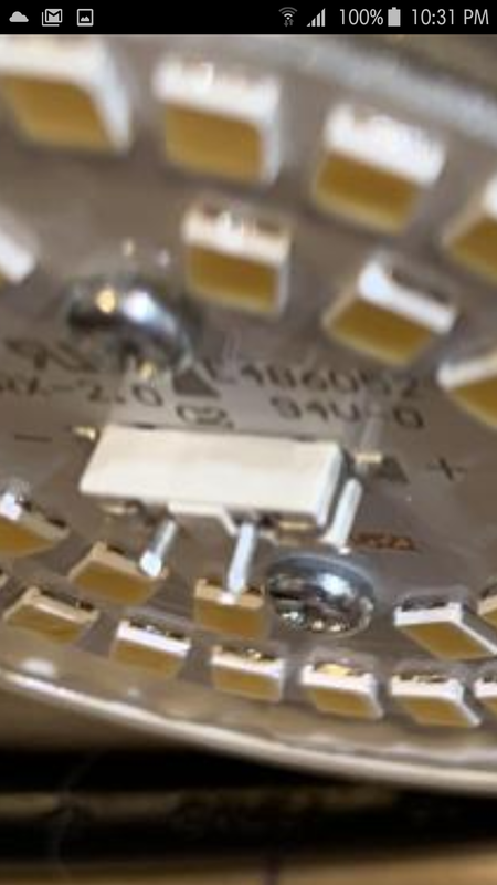
It's just a 10-ohm resistor with heat resistant "tubing" around it.


I'm going to leave the built-in driver and all the components alone and mount 5-6 on my cookie sheet.

I'm aiming for a 50-watt low profile overhead light.
It's more of an art project than a science one.
 

PCBuds

Well-known member
I noticed that this board has LEDs #7 & #8 replaced with LED #17.

Making it a little bit brighter than the original design.
 

PCBuds

Well-known member
The same bulb by the same company.

I like the one on the right. It's bigger and spreads the segments out more.


PCBuds

Well-known member
I just thought of something.

Maybe that resistor is used to warm up the bulb a bit for when it's being used outdoors in the winter?

I should put a bulb in the freezer and see if it is dimmer when I first turn it on.


Latest posts

Latest posts

Top