What's new
  • As of today ICMag has his own Discord server. In this Discord server you can chat, talk with eachother, listen to music, share stories and pictures...and much more. Join now and let's grow together! Join ICMag Discord here! More details in this thread here: here.

Off the shelf retail store screw-in LED and CFL bulb comparisons

PCBuds

Well-known member
I managed to Google it.


I don't think they're necessary.
Just add another led segment.

I think it's a scam.
Like when they came out with CFLs to save energy then you throw them away a few years later and buy LEDs.
Once we've all bought LED lights, we need to replace them with the newer more efficient LEDs.
 
Last edited:

f-e

Well-known member
Mentor
Veteran
It's not a ballast resistor. A ballast resistor is commonly used to run a perhaps 3v led, from a greater than 3v supply. Commonly found in 12v leds, where the ballast drops 9v across it, so the led gets the other 3. A wasteful circuit, as 75% of the power goes to heating the resistor.

All you have is a tiny resistance, to drop the smallest of voltages. Just enough to measure, and so calculate the current flow in the circuit

Edit: While counting led packages, we have forgotten the possibility of more than one being in there. Like mini cobs.

A dimmer for incandescent lighting just flashes the mains power on/off. Sometimes at zero cross? We don't notice because it's incandescent. Basically it aint cooling down that quick. This kind of dimmer can often only dim lamps from 40-250w. Due to the on time's minimum setting being too high for a low wattage. So your leds just see mains voltage being switched.
 

Hookahhead

Active member
I installed a little solar panel under the sunroof in my car and it's got a diode in it so power only goes into the battery but that thing on the SIL is a resistor and it only measures 0.09 ohms. (unless my ohmmeter isn't accurate at such a low resistance)

Oh yeah you’re absolutely right, I was getting a diode and resistor confused.
 

f-e

Well-known member
Mentor
Veteran
My bad, I'm guessing the resistor is for current calculation, but such values are often used as a fuse. I havn't seen the circuit to know.
 

indagroove

Well-known member
Veteran
Im pretty sure the resistor limits the flow of electrons to one direction. I believe this protects the circuitry... Ive seen this with solar panels so that they can only feed a battery and not drain it. I bet if you reverse the polarity (positive to negative and vise versa) the bulb won’t light up.

Resistors con't care about polarity, they only limit current.

I installed a little solar panel under the sunroof in my car and it's got a diode in it so power only goes into the battery but that thing on the SIL is a resistor and it only measures 0.09 ohms. (unless my ohmmeter isn't accurate at such a low resistance)

You won't be able to measure an accurate reading unless you physically remove the resistor from the circuit board.
 

PCBuds

Well-known member
It occurred to me that that resistor might be used as a thermistor.
As the "thermistor" heats up it increases it's resistance and helps control thermal runaway.
Most electronic devices increase their resistance as they get hot but LEDs reduce their resistance as they heat up and thermal runaway happens.

The color-code is brown black black gold so 10 ohms with a 5% tolerance.
Power equals I squared R, so 0.135 * 0.135 * 10 equals 0.18225 Watts.
Not that bad.

The resistor is located inside the base and is heated up from all sides.
A simple design and not that inefficient.

I found the bridge rectifier on the circuit board but it was too hard to remove or to try to solder two so I'm building a new one.

DB for double bridge?


PCBuds

Well-known member
I figured these things out.


They're little one way clips.
The circuit boards are produced then they can install wires, and in my case, a capacitor from the backside and the little clips bite into the wires to hold them in place.
 

indagroove

Well-known member
Veteran

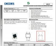
The MB10F diode does not have that type of internal schematic. It is bidirectional. Please take a look..

attachment.php
 

Attachments

  • Screenshot (22).jpg
    Screenshot (22).jpg
    61.1 KB · Views: 23

PCBuds

Well-known member
I always forget the polarity of a diode and direction of the current flow.


In electronics class, we were told to look at the symbol as a speaker and the sound from a speaker would come out on the left because current flows from negative to positive because electrons are negatively charged.

In physics class, we were told to look at the symbol as an arrow because the current would flow from positive to negative. The physicists were the ones who discovered that electrons were negatively charged. But what is a positive amount of negative things?

It gets confusing.

We had the right-hand rule in one class and the left-hand rule in the other.
 
Last edited:

Boocoodinkydow

Active member
I always forget the polarity of a diode and direction of the current flow.


[URL=https://i.postimg.cc/28shyjh7/Screenshot-2019-11-02-02-46-41.png]View Image[/url]


In electronics class, we were told to look at the symbol as a speaker and the sound from a speaker would come out on the left because current flows from negative to positive because electrons are negatively charged.

In physics class, we were told to look at the symbol as an arrow because the current would flow from positive to negative. The physicists were the ones who discovered that electrons were negatively charged. But what is a positive amount of negative things?

It gets confusing.

We had the right-hand rule in one class and the left-hand rule in the other.

I spent the majority of my adult career as a certified industrial electronics technician. I taught basic electronics course at our local trade school for 6 years back in the 80’s and later at the USPS technical training center in Norman, Oklahoma for a while.

I’ve been retired for better than 16 years now. Last year, curious to see how much I’d forgotten, I took a peek at an online electronics course. Confusing, no, just simply insane how theory has morphed from my heyday!! Seems much simpler to visualize the flow of electrons rather than the movement of holes!?!?:fsu::fsu:
 
Top