What's new
  • As of today ICMag has his own Discord server. In this Discord server you can chat, talk with eachother, listen to music, share stories and pictures...and much more. Join now and let's grow together! Join ICMag Discord here! More details in this thread here: here.

motor contactor help????????

mr cheese

Member
manitu said:
The most important stuff from the flip-flop thread:

The omron contactor is delivered in models from 24 to550V AC + many DC voltages.

ANY model can switch any voltage up to 600V at max the rated current, but they are made to start and stop big electric engines, and will handle spikes with higher voltage. (exept the "AR" model-only for single 400/600W)

You can hook up four extra switches on top of the contactor, controlling an additional ballast! On some omron model, you can use eight! extra switches, controlling a total of three ballasts.( or six, if you go the single-pole route)


N.O. means "Normally Open"(not connected), N.C. means "Normally Closed"(connected)!
So lamp no. 1 must use the two N.C. channels, and lamp no. 2 must use the N.O. channels.
When you apply voltage from the timer, the N.C channels open, and the N.O. channels close.

Maybe this makes more sense.(sorry for the shitty paint-drawings..)
internals:
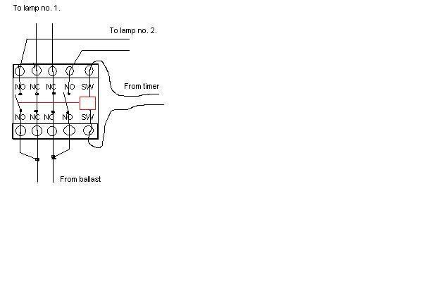
contactor2.jpg


.manitu


same as livewire said, nice one for all the help manitu.

quick q for ya, you see the wires coming from the ballast? youv draw 4 wires, but the ballast (bulb)wires from the ballast only have 2, is this just a miss print? just im goingt with this idea and dnt wana blow myself up,lol....nice1....mrc
 

cocktail frank

Ubiquitous
Mentor
ICMag Donor
Veteran
they are just jumped out from one terminal to another.
as long as the colors line up on the line and load side (l1,l2/ t1,t2)
only because the nc and no contacts have no physical contact side to side, just top to bottom.
 

ooga booga

Member
pastor420 said:
The main reason is that you aren't switching lights per se but rather the ballast. A light is primarily a resistive load as opposed to a ballast or motor that is more of a inductive load. The collapsing magnetic field of the inductor can cause voltage spikes that a resistive load can't cause.
I'm confused. Will this relay do the trick for controlling 3 x 1000w (@ 240V) lights?

http://www.grainger.com/Grainger/items/5Z546

Just want to move away from my Intermatic T104 and use a digital timer + DPST relay combination if it's OK to do so.

Or do I need something that says inductive, not resistive? :chin: :confused:

While I'm at it, will a similar SPST relay be OK to control a ~10A @ 120V air conditioner? I'd like to control it through the environmental controller's thermostat. Or the same inductive / resistive thing again? Got me all confused...

(Dayton 5Z546: Power Relay, Coil Voltage 120 VAC, Contact Current Rating Resistive @ 28 VDC 30 Amps, Contact Current Rating Resistive @ 300 VAC 30 Amps, Coil Current Rating 10VA, Power Rating @ 240 VAC 1.5 HP, Power Rating @ 480 VAC 1.5 HP, Contact Form Double Pole Normally Open, Contact Point 6)
 
Last edited:

Latest posts

Latest posts

Top