What's new
  • As of today ICMag has his own Discord server. In this Discord server you can chat, talk with eachother, listen to music, share stories and pictures...and much more. Join now and let's grow together! Join ICMag Discord here! More details in this thread here: here.
  • ICMag and The Vault are running a NEW contest in October! You can check it here. Prizes are seeds & forum premium access. Come join in!

lights turned off???....ballasts still on???

rives

Inveterate Tinkerer
Mentor
ICMag Donor
Veteran
1 question on your original problem. Were the coils active ( pulled in to the normally open position )? If they were not you can most likely rule out the relays.

What Tilt is talking about here is that when relays are being used for a flip-flop (alternately driving two lamps with one ballast), one lamp would be driven when the relay coil is energized (the normally open contacts), and the other lamp would be driven when the coil is de-energized (the normally closed contacts). If the lights went out when the coil was not energized, the relays would not be the problem because they would not have momentarily dropped power to the lamp (necessitating a cool-down, restrike cycle).

What Panama is talking about with the coil wiring is that you have two wires crimped together in each terminal on the coils. Each wire should have it's own terminal and then the two terminals screwed down together. Alternately, Tilt suggests pig-tailing the wires, which would mean there would be a single short length of wire coming from each coil connection which would then be wire-nutted to a main wire running from relay to relay.

The gutter suggestion is just that - a section of gutter running over the top of the electrical components to redirect any dripping water away from them.

The lexan idea that Tilt suggests is a clear, non-conductive plastic sheet mounted over the top of the components on stand-offs (spacers). This protects you from accidental contact with live equipment, but enables you to see what is going on.

Finally, unscrewing the lamps and leaving the ballasts hot is a very poor idea. By the way, you aren't getting fingerprints on the lamps when you screw them back in, are you? The oil from your fingerprints will break down the glass envelope of the lamp at the temperatures that they operate.
 
Rives, you asked for my input.....I'm not a sparky but I've learned a few things pursuing my hobby. The flip-flop stuff is over my head, I don't use them. Just the pics of 10 bare ballasts on plywood gives me the willies big-time. And the wiring of the components may be correct but having everything exposed (not in flex conduit) scares me too. I know I couldn't sleep soundly with that setup in my house...........

stagehand
 

Tactician

Member
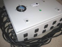
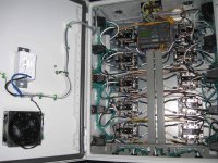
This is how a 10 ballast flip should be built. The enclosure is NEMA rated and all connections are ratchet crimped, internal fan, 14awg lampcords, green A/B indicator lights, digital AUBE timer, 10 x 600V/30A dpdt relays, Siemens PLC to flip one light per side at a time, 1 minute delays.
 

Attachments

  • 10 ballast flip inside view.jpg
    10 ballast flip inside view.jpg
    83 KB · Views: 13
  • 10 ballast flip.jpg
    10 ballast flip.jpg
    48.5 KB · Views: 10

zenoonez

Active member
Veteran
This is how a 10 ballast flip should be built. The enclosure is NEMA rated and all connections are ratchet crimped, internal fan, 14awg lampcords, green A/B indicator lights, digital AUBE timer, 10 x 600V/30A dpdt relays, Siemens PLC to flip one light per side at a time, 1 minute delays.

Damn I have to say that looks both beautiful and expensive. Lol.
 

joe fresh

Active member
Mentor
Veteran
What Tilt is talking about here is that when relays are being used for a flip-flop (alternately driving two lamps with one ballast), one lamp would be driven when the relay coil is energized (the normally open contacts), and the other lamp would be driven when the coil is de-energized (the normally closed contacts). If the lights went out when the coil was not energized, the relays would not be the problem because they would not have momentarily dropped power to the lamp (necessitating a cool-down, restrike cycle).

i dont know how the relays were cuz i didnt check them

What Panama is talking about with the coil wiring is that you have two wires crimped together in each terminal on the coils. Each wire should have it's own terminal and then the two terminals screwed down together. Alternately, Tilt suggests pig-tailing the wires, which would mean there would be a single short length of wire coming from each coil connection which would then be wire-nutted to a main wire running from relay to relay.

i dont get it...i dont see where there is 2 wires crimped together, maybe someone could explain with pics?

The gutter suggestion is just that - a section of gutter running over the top of the electrical components to redirect any dripping water away from them.

ok cool, i already fixed any condensation on the water pipes by insulating them, any un-unsulated copper pipeing is hot water and will not condensate, thx for the idea though

The lexan idea that Tilt suggests is a clear, non-conductive plastic sheet mounted over the top of the components on stand-offs (spacers). This protects you from accidental contact with live equipment, but enables you to see what is going on.

know where i can see this online so i can get an idea of what it looks like? so when i go to get it localy ill know where to look and what exactly to get....

Finally, unscrewing the lamps and leaving the ballasts hot is a very poor idea. By the way, you aren't getting fingerprints on the lamps when you screw them back in, are you? The oil from your fingerprints will break down the glass envelope of the lamp at the temperatures that they operate.

yeah i got a box of 1000 doc gloves that i use for just that and trimming....they are priceless, lol
 

Panama Red

Active member
What you currently have for control voltage wiring goes to the first relay then jumpers to the next and so on and so on.

The way it should be done is with a direct run from the control voltage direct to each relay.

Done properly, if there is one bad crimp or open wire, only that relay will be effected, not every one downstream.

A crude drawing.......

JF Relay.JPG

.
 

rives

Inveterate Tinkerer
Mentor
ICMag Donor
Veteran
This is how a 10 ballast flip should be built. The enclosure is NEMA rated and all connections are ratchet crimped, internal fan, 14awg lampcords, green A/B indicator lights, digital AUBE timer, 10 x 600V/30A dpdt relays, Siemens PLC to flip one light per side at a time, 1 minute delays.

Very nice work. My only question would be how much money was saved over running individual ballasts. Flip-flops have always seemed to have a pretty questionable r.o.i. to me.
 

joe fresh

Active member
Mentor
Veteran
What you currently have for control voltage wiring goes to the first relay then jumpers to the next and so on and so on.

The way it should be done is with a direct run from the control voltage direct to each relay.

Done properly, if there is one bad crimp or open wire, only that relay will be effected, not every one downstream.

A crude drawing.......

View attachment 85344

.


the red and green wires you have drawn, are they supposed to be from the ballasts?

if so , the wires running from the ballasts to the relays are direct and do not intercross between the relays.

the wires that doo cross are the 12/24v timer wires, you know...th ones that actually make the relays activate....

in the pic you drew i put blue circles for where my ballasts run directly to each individual relay, and red circles where the wires run from one relay to the other(which runs from the timer)


and to the guy who posted the pic of the "flip box", wow very impressive, but how much did that little piece of equipment cost?

my entire electrical setup cost me about 3500 including all relays, wire, electricians time, ballast/light instalation.....basicly i braught him the sub pannel and ballast/hoods, and paid him 3.5k and he supplied the rest....


my 10 ballasts cost me 1700, so imo i think i saved 1700 by going the relay route, instead of getting 10 extra ballasts, 3 extra timers.....ect.....

but if i were to have to do it all over again, i might opt for him just wireing my swubpannel, and id do the rest.

i just setup a friends house 8k grow and it was simple, the only thing that complicates things is the relays....PIA, but i got them and now have to deal with them......
by getting
 

Attachments

  • JF Relay.JPG
    JF Relay.JPG
    69.3 KB · Views: 11

joe fresh

Active member
Mentor
Veteran
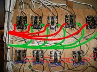
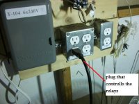
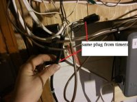
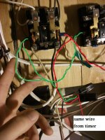
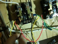
heres a few pics with colored wires....i didnt label it properly, but .....one plug from timer going to first relay, then small thin wires going from relay to relay.

first relay in line is bottom left, then goes all to the far right, then up to the top right relay , then all to the far left....

like


finish--- O<--O<--O<--O<--O

start---- O-->O-->O-->O-->O
 

Attachments

  • DSCF1734.JPG
    DSCF1734.JPG
    40.2 KB · Views: 11
  • DSCF1735.JPG
    DSCF1735.JPG
    41.8 KB · Views: 10
  • DSCF1736.JPG
    DSCF1736.JPG
    54.2 KB · Views: 10
  • DSCF1737.JPG
    DSCF1737.JPG
    54.2 KB · Views: 13

Panama Red

Active member
The red and green wires I drew are NOT supposed to be from the ballasts, they're represent the way the control voltage from the timer is SUPPOSED to be wired.

Each relay should have it's own discrete run from the timer (or back where you have wire nuts holding it together) instead of being jumped from relay to relay.

A side note; you mentioned "12/24v timer wires" but those originate from a 110v receptacle. WTF??
 

joe fresh

Active member
Mentor
Veteran
ok cool that makes sense....

but yeah....i was assuming that it was 12/24v but now that i look at it it seems that in my sub pannel i have a 30amp breaker dedicated to the timer, and from what i can tell my timer is powered by 220/240v, is this possible? the plug outlets built in the timer are also 220/240v i believe, as i remember when i went to buy my lights and timer i asked the guy at the hydro store for 220/240v on everything....so im assuming he gave me a 240v timer along with the 240v ballasts....

but how could the relays work if they are on 240v? is it possible that these relays are 220/240v? or did my electrician just make another short cut?

and if he wired them wrong (220/240), then how have they been working for soo long?(im assuming when you put a 240v wire to 12/24v plug, that the plug wouldnt last too long)

EDIT- i checked and it says right on the timer "6 x 240v" which is refering to the outlets


on a side note, all my plugs and receptables are 110v plugs(the hydro store sells them like that, and makes it easier for plug/play....imo)
 

Panama Red

Active member
Those could possibly be 240v driven relays.

Why your electrician used a 110v outlets is beyond me.

Just one last question.

He charged you $3.5K to build that relay panel so you could save $1.7K on 10 more ballasts?

Forget learning how to use that multimeter, you need a calculator.......
 

joe fresh

Active member
Mentor
Veteran
nono...lol....hahaha


he cost 3500 including all wire, subpanel....and im *** grid;)....i basicly put my ballasts in my house....gave him 3500 and he did the rest, except for the a/c's(had the a/c guy do those)

the next house he cost me 4500 and i did all the wireing and ballast instalation(no relays), all he did was put me *** grid and install my subpannel
 

Latest posts

Latest posts

Top