Hello there every1, how are we today?
I have been promising to do this thread now for a few weeks, and after some help with the wiring, ive cracked it. I havent included pics of every single wiring connection as not every1 will get the same thermostat as me, but i will show a diagram of the wiring for this thermostat for the folks who do.
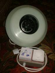
Now, before we start, what exactly does it do?? It does exactly what it sounds like, it controls the speed of ur fan thermostatically. Basically, this little gizmo lets you lower the speed of your extractor fan for noise reduction/power conservation and if ur fan is just too powerful, and also if the fan you got for those hot summer temps is now too much in the winter. But whats good about this gadget is that by use of the thermostat, the fan can turn over at lower speeds, but when the temperature hits a predetermined level ((which is set by the knob on the thermostat)) the fan jumps into full power, and runs on full until the temperature drops back down below the level you set. This means that hopefully with a little adjustment, your growroonm should stay at nice steady temperauture, and you can relax safe in the knowledge that your green darlings are not being slowly cooked, but that ur fan is only using the electricity it needs to.
So, here we go, for this little project, you will need.....
1x Fan speed controller of your choice(i got mine from B and Q, it is a 250 watt model) Make sure you get a fan speed controller and not a dimmer switch if you are getting your speedo from a DIY store, if it hasnt got a fan printed on the knob its a dimmer!!. You can also use a speedo made by ur fans manufacturer if you wish-but check the wiring.
1x Cooling thermostat ( I used a Danfoss RMT230 heating/cooling stat, the honeywell T6360 is another recommended one, the wiring plan for which can be found at uk420).
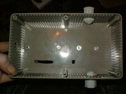
1x Plastic rectangular junction box, big enough to fit the hardware onto.
2x Cable retention glands ((PLASTIC!)).
2 lengths of heat resistant 3 core elecrtical cable, 1 long enough to reach the power outlet from the controller, and one long enough to reach the fan from the controller.
Some stripped inner wires from the cable.
4x Terminal crimp connectors ((optional but tidier))
4x`Small nuts and bolts to fit hardware onto box.
1x Eye bolt and nut.
1x Mains plug.
The tools you will need are
1 set of wire strippers.
1x Drill with small bit to match bolts.
1x small flathead screwdriver.
1x Medium Crosshead screwdriver.
1x Pliers.
The 1st job that needs to be done, is to mark out the positions for the speedo and stat on the box with a marker pen, marking around them, and also marking the fixing points where holes need to be drilled.
Once it is all marked up you can drill the holes required to feed the wiring to the hardware from inside the box. I made a single hole for the wires to the speedo and a longer slit for the thermostat wires.

After these holes are made and the edges smoothed off you can fix the thermostat and surface mounting box onto the wiring box.

Now the wiring begins.

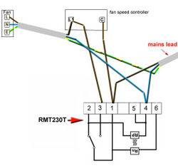
The exact wiring differs with different thermostats, but for this danfoss RMT230 ive used it is as follows
Power cord connections.
Live to thermostat terminal 1.
Neutral to thermostat terminal 4.
Earth to strip connector.
Fan cord connections.
Live to Speedo L1
Neutral to thermostat terminal 4
Interior connections.
1 length of brown(live) from thermostat terminal 3 to speedo L1
1 length of brown(live) from thermostat terminal 1 to speedo C
I have a diagram but its in the wrong format to put it up(apparently) so ill have to copy one out for here later.
Now this wiring is comlete, you are`almost finished, you just need to screw the speedo down on to the surface mounting box, and put the thermostat cover and knob back on.
Now you should hook it up to a fan and test it before it goes into your growroom

And mine works a treat. The easiest way to test it is to turn it on, lower the speed, and then turn the thermostat down to just lower than the temperature of the room you are in, it should click the stat on and the fan flip into full power.
All thats left is to mark the minimum and maximum points on the speed control and its ready to install.
This is a great bit of kit and has cost me 30 pounds to make. To buy one of these in the growshops is around 100 pounds although granted that one is a bit prettier, but for less than 1/3rd of the price who cares about pretty.
I am only using it for extraction control with passive intakes, but if you are using a dual fan setup, you can control the speed of both with this if the fans total power doesnt go over 250 watts, but it would be better to add a second speed control to control a second fan!
I plan to update this thread as i modify/expand this, eventually into a complete enviromental controller. The 1st modification will be to swap the mechanical thermostat for a digital programmable one. with a programmable stat the enviroment can be even more finely tuned with several time zones through the day, with the temperature being able to be set different at different times. this would allow the setting of a lower temperature at night than in the day and be more like the natural world!
Another good addition would be a Humidistat also wired in to override the speed controller when the humidity reaches a preset level. This is what i am looking into right now, trying to find out if it will work.
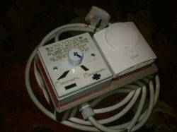
So, without further ado, here it is....

complete with note to remind me it buzzes less if the fan is switched on at full speed and the speed turned down after switch on instead of switching on at a low speed-it really makes a lot of difference for some reason.
Well that is all done, I hope to see some of these appearing around here soon.
I cant take credit for this design, the origional was done by "Fazered" at UKCultivator some time ago. That origional design had the speedo and stat mounted seperately on lengths of cable connecting in a small junction box. I have just changed it up a bit.
I must also say a very big thank you to OT1 over at UK420, for being super helpful and translating the wiring of the fazfan into a proper wiring diagram with the right wiring colours, and giving me the correct wiring for this thermostat, which is not the one used the origional. So many thanks to OT1, and much respect to Fazered for the inspiration.
right, that'll just about do it I think, Time to go now, i wanna go and fit my new gizmo into my room....
hope you all like my little contribution.
Catch you all later,
Be lucky now
{EDIT} Here is the wiring diagram that i finally remembered to add..

I have been promising to do this thread now for a few weeks, and after some help with the wiring, ive cracked it. I havent included pics of every single wiring connection as not every1 will get the same thermostat as me, but i will show a diagram of the wiring for this thermostat for the folks who do.
Now, before we start, what exactly does it do?? It does exactly what it sounds like, it controls the speed of ur fan thermostatically. Basically, this little gizmo lets you lower the speed of your extractor fan for noise reduction/power conservation and if ur fan is just too powerful, and also if the fan you got for those hot summer temps is now too much in the winter. But whats good about this gadget is that by use of the thermostat, the fan can turn over at lower speeds, but when the temperature hits a predetermined level ((which is set by the knob on the thermostat)) the fan jumps into full power, and runs on full until the temperature drops back down below the level you set. This means that hopefully with a little adjustment, your growroonm should stay at nice steady temperauture, and you can relax safe in the knowledge that your green darlings are not being slowly cooked, but that ur fan is only using the electricity it needs to.
So, here we go, for this little project, you will need.....
1x Fan speed controller of your choice(i got mine from B and Q, it is a 250 watt model) Make sure you get a fan speed controller and not a dimmer switch if you are getting your speedo from a DIY store, if it hasnt got a fan printed on the knob its a dimmer!!. You can also use a speedo made by ur fans manufacturer if you wish-but check the wiring.
1x Cooling thermostat ( I used a Danfoss RMT230 heating/cooling stat, the honeywell T6360 is another recommended one, the wiring plan for which can be found at uk420).
1x Plastic rectangular junction box, big enough to fit the hardware onto.
2x Cable retention glands ((PLASTIC!)).
2 lengths of heat resistant 3 core elecrtical cable, 1 long enough to reach the power outlet from the controller, and one long enough to reach the fan from the controller.
Some stripped inner wires from the cable.
4x Terminal crimp connectors ((optional but tidier))
4x`Small nuts and bolts to fit hardware onto box.
1x Eye bolt and nut.
1x Mains plug.
The tools you will need are
1 set of wire strippers.
1x Drill with small bit to match bolts.
1x small flathead screwdriver.
1x Medium Crosshead screwdriver.
1x Pliers.
The 1st job that needs to be done, is to mark out the positions for the speedo and stat on the box with a marker pen, marking around them, and also marking the fixing points where holes need to be drilled.
Once it is all marked up you can drill the holes required to feed the wiring to the hardware from inside the box. I made a single hole for the wires to the speedo and a longer slit for the thermostat wires.
After these holes are made and the edges smoothed off you can fix the thermostat and surface mounting box onto the wiring box.
Now the wiring begins.
The exact wiring differs with different thermostats, but for this danfoss RMT230 ive used it is as follows
Power cord connections.
Live to thermostat terminal 1.
Neutral to thermostat terminal 4.
Earth to strip connector.
Fan cord connections.
Live to Speedo L1
Neutral to thermostat terminal 4
Interior connections.
1 length of brown(live) from thermostat terminal 3 to speedo L1
1 length of brown(live) from thermostat terminal 1 to speedo C
I have a diagram but its in the wrong format to put it up(apparently) so ill have to copy one out for here later.
Now this wiring is comlete, you are`almost finished, you just need to screw the speedo down on to the surface mounting box, and put the thermostat cover and knob back on.
Now you should hook it up to a fan and test it before it goes into your growroom
And mine works a treat. The easiest way to test it is to turn it on, lower the speed, and then turn the thermostat down to just lower than the temperature of the room you are in, it should click the stat on and the fan flip into full power.
All thats left is to mark the minimum and maximum points on the speed control and its ready to install.
This is a great bit of kit and has cost me 30 pounds to make. To buy one of these in the growshops is around 100 pounds although granted that one is a bit prettier, but for less than 1/3rd of the price who cares about pretty.
I am only using it for extraction control with passive intakes, but if you are using a dual fan setup, you can control the speed of both with this if the fans total power doesnt go over 250 watts, but it would be better to add a second speed control to control a second fan!
I plan to update this thread as i modify/expand this, eventually into a complete enviromental controller. The 1st modification will be to swap the mechanical thermostat for a digital programmable one. with a programmable stat the enviroment can be even more finely tuned with several time zones through the day, with the temperature being able to be set different at different times. this would allow the setting of a lower temperature at night than in the day and be more like the natural world!
Another good addition would be a Humidistat also wired in to override the speed controller when the humidity reaches a preset level. This is what i am looking into right now, trying to find out if it will work.
So, without further ado, here it is....
complete with note to remind me it buzzes less if the fan is switched on at full speed and the speed turned down after switch on instead of switching on at a low speed-it really makes a lot of difference for some reason.
Well that is all done, I hope to see some of these appearing around here soon.
I cant take credit for this design, the origional was done by "Fazered" at UKCultivator some time ago. That origional design had the speedo and stat mounted seperately on lengths of cable connecting in a small junction box. I have just changed it up a bit.
I must also say a very big thank you to OT1 over at UK420, for being super helpful and translating the wiring of the fazfan into a proper wiring diagram with the right wiring colours, and giving me the correct wiring for this thermostat, which is not the one used the origional. So many thanks to OT1, and much respect to Fazered for the inspiration.
right, that'll just about do it I think, Time to go now, i wanna go and fit my new gizmo into my room....
hope you all like my little contribution.
Catch you all later,
Be lucky now
{EDIT} Here is the wiring diagram that i finally remembered to add..

Last edited:


 how is the big one comin


