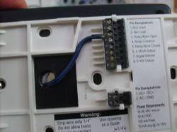
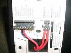
First off...
That being said... Ide like to thank everyone who gave me input and support... You guys rock : )
I am sure there are other ways of doing this... I started to doubt the need for the extra SPDT relay, but I will address that at the end.
On with the plans... Here she blows...

The specs...
Measures 0-10,000ppm (Adjustable range... I have it set to 0-3,000)
Adjustable Histeris
Adjustable Setpoint (NO/NC contacts)
Adjustable Elevation (supposedly makes the reading more accurate... default is set at sealevel)
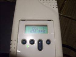

What you need...

Telaire 8001 or 8002 Ventostat (I used an 8002, only difference is the 8001 doesnt have a keypad or LCD and has to be configured through a computer). This is the brains... it is what measures the CO2 and signals to the relay when give power to the outlet.
120v (Primary) to 24v (Secondary) Step-Down Transformer - provides power to the ventostat -
24v coil SPDT line voltage relay - this is what switches the outlet from having power or not....
wall outlet /w faceplate - i bought a double one because it was cheaper than a single... doesnt matter as long as you know not to plug in high draw devices into it.
pig-tail power cord- I butchered up an old computer power cable...
plastic project box 3x5x7 - purcahsed it at radioshack... houses all the electronics
box of wirenuts
some spare wire
few random screws/bolts/nuts laying around the house...
Other tools..... dremel... drill... screwdrivers
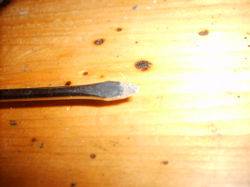
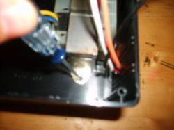
Step 1 - Plan out how you want to arrange the outlet, transformer, and relay inside the box. I started with the transformer. I mark the mounting holes with a screwdriver and then drilled them out.
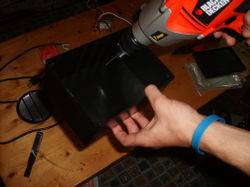

Then used some small screws + nuts to secure it to the box.

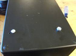
Next I removed the cover metal from my SPDT relay. Your relay may not look like this and hence other steps may be neccessary to mount it to your enclosure.

I then took a dremel with a sander bit and sanded away an indention similiar to the one already present for the blue wires...
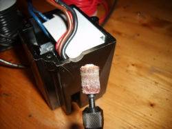
Next I placed the relay in it's position and then proceeded to mark the mounting holes with the screwdriver.
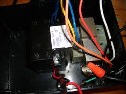
Drilled out a pilot for the mounting holes.

Then used the screws from the metal cover to secure the relay in place. The relay I used had a conduit connector that acted as a passive exhaut.... I drilled a few vent holes on the project box where the relay was goin to be mounted... the vent holes are not pictured.

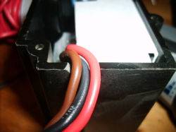
Next I drilled a hole from the incoming 120v power cord... It was slightly smaller than the cord and required a decent to tug to get the cord through.

Next....
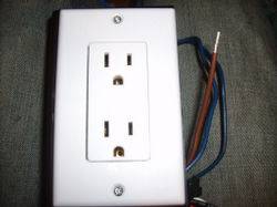
Took the dremel and used it to make a mounting hole for the outlet.

Then I proceeded to mark and drill out the pilot holes.

Here is how it looks mounted... No need to mount it yet... Still need to wire it up.
*WARNING* I am in no way responsible for any positive or negative effects that may entail from using this device (crop loss, fire... etc....) I did this on my own time, and in no way am I a certified electrician. To the best of my knowledge it is safe..... but it is NOT UL listed lol...
That being said... Ide like to thank everyone who gave me input and support... You guys rock : )
I am sure there are other ways of doing this... I started to doubt the need for the extra SPDT relay, but I will address that at the end.
On with the plans... Here she blows...

The specs...
Measures 0-10,000ppm (Adjustable range... I have it set to 0-3,000)
Adjustable Histeris
Adjustable Setpoint (NO/NC contacts)
Adjustable Elevation (supposedly makes the reading more accurate... default is set at sealevel)


What you need...

Telaire 8001 or 8002 Ventostat (I used an 8002, only difference is the 8001 doesnt have a keypad or LCD and has to be configured through a computer). This is the brains... it is what measures the CO2 and signals to the relay when give power to the outlet.
120v (Primary) to 24v (Secondary) Step-Down Transformer - provides power to the ventostat -
24v coil SPDT line voltage relay - this is what switches the outlet from having power or not....
wall outlet /w faceplate - i bought a double one because it was cheaper than a single... doesnt matter as long as you know not to plug in high draw devices into it.
pig-tail power cord- I butchered up an old computer power cable...
plastic project box 3x5x7 - purcahsed it at radioshack... houses all the electronics
box of wirenuts
some spare wire
few random screws/bolts/nuts laying around the house...
Other tools..... dremel... drill... screwdrivers
Step 1 - Plan out how you want to arrange the outlet, transformer, and relay inside the box. I started with the transformer. I mark the mounting holes with a screwdriver and then drilled them out.


Then used some small screws + nuts to secure it to the box.


Next I removed the cover metal from my SPDT relay. Your relay may not look like this and hence other steps may be neccessary to mount it to your enclosure.

I then took a dremel with a sander bit and sanded away an indention similiar to the one already present for the blue wires...


Next I placed the relay in it's position and then proceeded to mark the mounting holes with the screwdriver.

Drilled out a pilot for the mounting holes.

Then used the screws from the metal cover to secure the relay in place. The relay I used had a conduit connector that acted as a passive exhaut.... I drilled a few vent holes on the project box where the relay was goin to be mounted... the vent holes are not pictured.

Next I drilled a hole from the incoming 120v power cord... It was slightly smaller than the cord and required a decent to tug to get the cord through.

Next....
Took the dremel and used it to make a mounting hole for the outlet.

Then I proceeded to mark and drill out the pilot holes.

Here is how it looks mounted... No need to mount it yet... Still need to wire it up.

Last edited:


