
-
ICMag and The Vault are running a NEW contest! You can check it here. Prizes are seeds & forum premium access. Come join in!
You are using an out of date browser. It may not display this or other websites correctly.
You should upgrade or use an alternative browser.
You should upgrade or use an alternative browser.
150w HPS Club and Resource Guide......
- Thread starter Pipedream
- Start date
 I hope I will post more shots later. Breeder who gave me that seed told that the mother was durban x skunk (green pheno) pollinated by hollands hope.
Some nice looking buds there people !

(1) Remove bulb
(2) Remove metal reflection panel from inside of reflector (4 screws)
(3) Remove ballast from reflector (6 screws)
The ballast and reflector are now only attached by 2 wires (1 black, 1 white) going from the ballast to the bulb socket.
All you have to do is splice these 2 wires and extend them using an electrical cord. I bought an electrical cord at Home Depot today (12 feet and it costs 2 bucks) and that worked just fine. There are multiple ways to connect the wires, I just bought a small roll of electrical tape and used that.
Make sure that white goes to white and black goes to black. In my case, the electrical cord I was using was white - white, so I just marked one of the wires with a black magic marker, so I didn't get the wires mixed up when connecting them.
After the wires are spliced and taped up, all you have to do is screw the metal reflector sheet back in, put the bulb back in, and that's it really. I look forward to cooler temperatures in the cabinet soon, especially when the warm weather starts to kick in here.
Oh, and one last thing, even though I haven't gotten around to doing it yet, (I don't have a drill). When you remove the ballast from the reflector, the two metal strips on top that lets you mount the reflector to the ceiling are now seperated. And if you plan to hang the the reflector in the same fashion as before (the footprint will be smaller of course), then you just have to drill 2 small holes on top of the reflector and move the metal strip from the ballast to the reflector.


REMOTE BALLASTING 150 WATT - FLORALUX
I received a PM today from OldPathBluSky asking how I remote ballasted my 150 floralux. I asked a question about that on this thread earlier, but I didn't get around to doing it yet since I was in the middle of a grow. My last grow just finished less than a week ago, and I actually got around to remote ballasting the floralux just today ! So the timing of his question was pretty good, lol. It was pretty simple to do, even for a non-handyman person like myself.(1) Remove bulb
(2) Remove metal reflection panel from inside of reflector (4 screws)
(3) Remove ballast from reflector (6 screws)
The ballast and reflector are now only attached by 2 wires (1 black, 1 white) going from the ballast to the bulb socket.
All you have to do is splice these 2 wires and extend them using an electrical cord. I bought an electrical cord at Home Depot today (12 feet and it costs 2 bucks) and that worked just fine. There are multiple ways to connect the wires, I just bought a small roll of electrical tape and used that.
Make sure that white goes to white and black goes to black. In my case, the electrical cord I was using was white - white, so I just marked one of the wires with a black magic marker, so I didn't get the wires mixed up when connecting them.
After the wires are spliced and taped up, all you have to do is screw the metal reflector sheet back in, put the bulb back in, and that's it really. I look forward to cooler temperatures in the cabinet soon, especially when the warm weather starts to kick in here.
Oh, and one last thing, even though I haven't gotten around to doing it yet, (I don't have a drill). When you remove the ballast from the reflector, the two metal strips on top that lets you mount the reflector to the ceiling are now seperated. And if you plan to hang the the reflector in the same fashion as before (the footprint will be smaller of course), then you just have to drill 2 small holes on top of the reflector and move the metal strip from the ballast to the reflector.
Last edited:
OldPathBluSky
Member
Thanks for putting that info up! It's going to make my cab ready for the summer... thanks again.
Greenhead, I'm just curious how you knew which white wire was which? Did you ring them out before marking?
hoosierdaddy said:Greenhead, I'm just curious how you knew which white wire was which? Did you ring them out before marking?
Do you mean on the extension cord I used ?
I'm not sure what you mean by ring them out ?
My extension cord was white-white, so I just followed the path of one of the wires for the entire 12 feet, and marked it, so I could tell the difference between the two white wires.
Shady Smoka
Active member
Sounds to me like you used a real light duty cord. I hope its at least 14awg. And you shouldve prolly used wire some wire nuts, imo. Just my 2 cents.
Be safe
PS
Have you checked out SugaBears thread about wiring up a remote ballasted security light? Some pretty good info there
Be safe
PS
Have you checked out SugaBears thread about wiring up a remote ballasted security light? Some pretty good info there
Last edited:
Shady Smoka said:Sounds to me like you used a real light duty cord. I hope its at least 14awg. And you shouldve prolly used wire some wire nuts, imo. Just my 2 cents.
Be safe
PS
Have you checked out SugaBears thread about wiring up a remote ballasted security light? Some pretty good info there
The original cord going from the ballast to the reflector was pretty thin, and the extension cord I used was thicker than the original wire even.
I'm not sure what 14 awg is.
The specs on the cord I bought is 16 gauge, 13 amp, 125 v - 1625 watts max -
Also, thanks for the wire nuts suggestion. I'm going to pick up a couple of those today, and use them also.
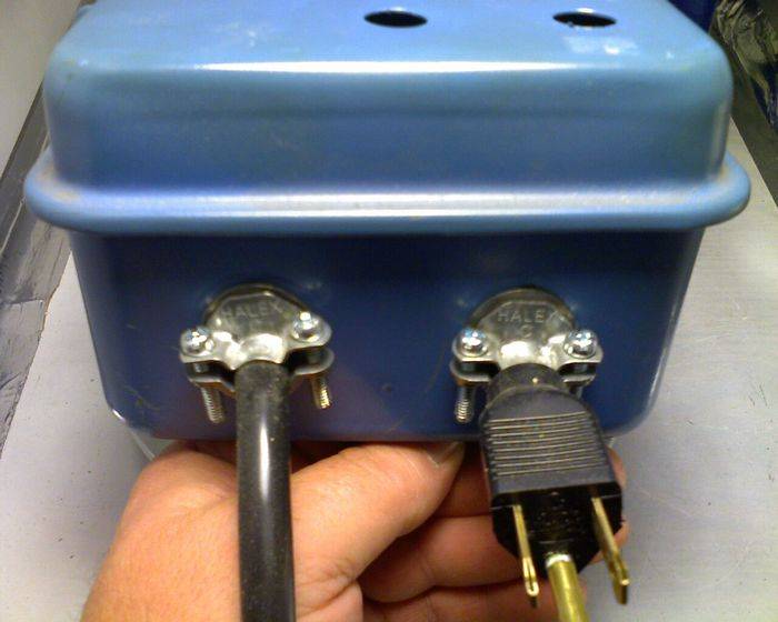
This is a picture of the cord I'm using, and how the floralux looks when the ballast is seperated.


Last edited:
Yeah, I'm like smokah, if you had at least 14AWG wire in the cord, it would probably be jacketed so that you would not know which wire was which from one end to the other. No way to "follow" the conductors in a round jacketed cable.
"Ringing" a wire out is simply checking for continuity. A meter (which we should all have even if a cheapo $8) will allow you to put the probes on the ends of the wires, and when you have the probes on the same wire ends, the needle will show it...or it will make a tone (or "ring") with some models to let you know you got the right wire.
(edit) OK, if yur wire is 16 gauge, that means it is 16AWG stranded wire. One gauge smaller than the suggested 14AWG.
Amperage is the key to wire size. Too many amps for the wire and heat starts to be created...not a good thing at all.
16AWG can carry about 22 amps, where as 14AWG can comfortably carry about 32 amps. (this can vary depending on type of wire and what you are doing with it)
I AM NOT AN LICENSED ELECTRICIAN
I think any of us who are no licensed should add this disclaimer to any electrical advice we give. I see many boneheads in hear passing around completely ignorant info (read heads up their ass and shouldn't be commenting).
Last edited:
hoosierdaddy said:No way to "follow" the conductors in a round jacketed cable.
I don't claim to know anything about electrical stuff, but the cord I was using is flat, and there is a left and right side even though both sides are white. I don't see why somebody can't follow one side from one end to the other. My HPS didn't blow up up when I turned it on, lol.
hoosierdaddy said:One gauge smaller than the suggested 14AWG.
Wouldn't the best suggestion be to use the same gauge that the original wire is ? The original wire is not being removed, just extended.
I AM NOT A LICENSED ELECTRICIAN
I would never use lamp cord (any flat cord) for anything I am DIYing. If it already has it, and I cut into it at all, I will replace it with a good quality round cable of the proper size to carry the required amperage. But that's just me.
The round cable extension cord you show is fine to use. Stranding and quality of wire can be pretty shoddy (and different from a cord using same gauge wire) in a flat Chinese lamp cord.
DiscoDuck
Member
greenhead, when your fixture was combined (lamp and ballast) the enitre unit was grounded (probably to the ballast.) Since you've remoted the fixture, (nice job by the way) the "remote" part is no longer grounded. For safety, you could run a 14 gauge insulated wire from the ground post on the ballast to a suitable ground (metal to metal) on the fixture. Scratch off paint if necessary.
I'm not an electrician but the 14 awg wire running from my ballast to fixture is cool to the touch after running 12 hrs. It might be a good idea to check yours and see if there's any heat, if so change to 14 awg. The wires inside the fixture/ballast are small gauge but they're also very short and very high quality. How long is your extension? The longer it is the more critical the correct gauge. hoosierdaddy may have a good point about the lower quality Chinese copper used in those flat extension cables.
Sugabear has a tutorial in the diy thread. He uses a 3 conductor (insulated ground included) extension cord. It's exactly the same process as yours but it includes the ground and you can conveniently unplug the fixture from the ballast for transport, maintenance, etc. He specifically recommends a grounded fixture for safety.
Jacketed (round) wire is color coded (black, white, green) just like the wires in your lamp. (The ground in your lamp may be bare copper wire.) When/if you attach an electrical plug to the extension, it's necessary to get the polarity correct. The black and white (hot and neutral) wires have to be connected to the correct flats on the plug and receptacle. I initially explained which color goes on which flat, but I've since seen conflicting information on this. Maybe one of our resident electricians can clear this up for us.
There is a chance that you'll never have an issue with the 16 awg. Think of the lengthy hours you'll spend away from your grow. It'll cost less than $12.00 to re-wire your remote fixture with a ground and will then pass code. A plus is you'll have a handy plug/unplug option you'll fall in love with.
Last edited:
BRNEYDBVR
Active member
Greenhead....
hoosier and Disco are giving you solid advice...
I didn't have to remote my 150.... I actually found a friend who did it for me, but like they have said.... 14 awg wire was used, and an old green ammo can as a ballast box. Almost 2 years old now, and haven't had a problem.
That's why this thread is so awesome... Good, solid advice that you can count on.
Keep it green.
DiscoDuck
Member
greenhead said:I don't claim to know anything about electrical stuff, but the cord I was using is flat, and there is a left and right side even though both sides are white. I don't see why somebody can't follow one side from one end to the other. My HPS didn't blow up up when I turned it on, lol.
Wouldn't the best suggestion be to use the same gauge that the original wire is ? The original wire is not being removed, just extended.
hey greenhead, forgot to mention your 2 way flat cord is coded on the white insulation. You'll probably have a bead running the length of one wire while the other wire is smooth. Otherwise the insulation will have some sort of identification printed on it. This printed info is on one strand, the other isn't marked.
DiscoDuck said:hey greenhead, forgot to mention your 2 way flat cord is coded on the white insulation. You'll probably have a bead running the length of one wire while the other wire is smooth. Otherwise the insulation will have some sort of identification printed on it. This printed info is on one strand, the other isn't marked.
Hey, you're absolutely right ! I just took a closer look at the cord and indeed, one is smooth and the other has a few tiny lines on it ! I luckily got it right just using the finger method, but in the future I will know that there are far, far easier ways of determining which wire is which, thanks !
Also, thanks to everybody who's replied with info ! I certainly don't want to do anything that would pose an electrical danger.
What you said about the fixture and ballast being grounded before, because they were physically connected makes a lot of sense, and now the fixture is not, because they are seperated. Before I go fiddling around and taking apart the ballast just yet, I'm going to read up some more on this stuff, and if it's not that difficult, I'll just pick up a heavier duty cord w/ ground and I'll rewire using that, and I'll eliminate the original cord completely.
Last edited:
Like the Duckster mentioned, when you remote the ballast with a two conductor cable, you have essentially taken the ground out of the picture. The light may run fine, or it may not, because a HPS can "cycle" similar to what an old worn bulb may do, if it is not properly grounded. I think (I AM NOT A LICENSED ELECTRICIAN) that it can also mess with the igniter and cause it to degenerate faster than normal.
The three prong plug that goes into the power socket is earth grounded, and as long as you run a stranded wire (I suggest 14AWG) from the metal of the light fixture as you have it now, back to the ballast box that uses the three prong grounded plug, you will be fine. This also protects you from dying instead of just having your bell rung if you would happen to get conducted and become the ground.
I figure that if I am going to offer up this advice, I may as well post up pics and do it right...
I bought two of the $20 150wHPS from Econolights. The unit is originally all mounted together ballast and light fixture, which is grounded by the three pronged plug-in.
When I remoted the ballast, I no longer had a grounded light fixture.
So, I had to run one.
First my ballast.
It has been mounted in a used Intermatic timer box.

Note that I used cheap cord grips to enter the box with the power cord on the left, and the light fixture plug on the right.

For the light fixture plug, I used the male end on the box, and the female end is on the light fixture. This is so that you can never hose up and plug the light into a regular 115vac receptacle. It also helps if you would (heaven forbid) call your old lady from jail and tell her to plug up your light for you. It's also a good idea to keep this backwards plug short, so you can't plug it into a receptacle. Basically it a dummy proof move.

You can see where the power cords ground wire (green) gets attached to a grounding lug that the box had...you can improvise and screw it into the metal yourself if there is no lug.

Now, I want this cheapo to last a bit so I use aluminized insulation board to make a heat barrier between the transformer and the igniter. Heat is what kills the igniter.

When the box is closed I have two holes for heat escape. The insulation channels the heat to these holes and the ignioter is cool as a cucumber all the time.

My light fixture is mounted to an aluminum channel, so I used a 14AWG wire and screwed it into the metal of the light fixture, and ran the wire back to the ballast room. Note that by rights, this wire should be green to signify it is a ground, but I only have red wire.

I then drilled a hole in the side of the ballast box and attached the grounding wire.

Everything is good to go, and I am not nervous about having a shoddy electrical device in my cabinet.
I have two lights hooked up to the aluminum channel, but I only need one ground for both since they are on once common piece of metal.
Hope this helps some folks.
HD
The three prong plug that goes into the power socket is earth grounded, and as long as you run a stranded wire (I suggest 14AWG) from the metal of the light fixture as you have it now, back to the ballast box that uses the three prong grounded plug, you will be fine. This also protects you from dying instead of just having your bell rung if you would happen to get conducted and become the ground.
I figure that if I am going to offer up this advice, I may as well post up pics and do it right...
I bought two of the $20 150wHPS from Econolights. The unit is originally all mounted together ballast and light fixture, which is grounded by the three pronged plug-in.
When I remoted the ballast, I no longer had a grounded light fixture.
So, I had to run one.
First my ballast.
It has been mounted in a used Intermatic timer box.

Note that I used cheap cord grips to enter the box with the power cord on the left, and the light fixture plug on the right.
For the light fixture plug, I used the male end on the box, and the female end is on the light fixture. This is so that you can never hose up and plug the light into a regular 115vac receptacle. It also helps if you would (heaven forbid) call your old lady from jail and tell her to plug up your light for you. It's also a good idea to keep this backwards plug short, so you can't plug it into a receptacle. Basically it a dummy proof move.

You can see where the power cords ground wire (green) gets attached to a grounding lug that the box had...you can improvise and screw it into the metal yourself if there is no lug.

Now, I want this cheapo to last a bit so I use aluminized insulation board to make a heat barrier between the transformer and the igniter. Heat is what kills the igniter.

When the box is closed I have two holes for heat escape. The insulation channels the heat to these holes and the ignioter is cool as a cucumber all the time.

My light fixture is mounted to an aluminum channel, so I used a 14AWG wire and screwed it into the metal of the light fixture, and ran the wire back to the ballast room. Note that by rights, this wire should be green to signify it is a ground, but I only have red wire.

I then drilled a hole in the side of the ballast box and attached the grounding wire.

Everything is good to go, and I am not nervous about having a shoddy electrical device in my cabinet.
I have two lights hooked up to the aluminum channel, but I only need one ground for both since they are on once common piece of metal.
Hope this helps some folks.
HD
Very nice writeup hoosierdaddy.
I was looking around and I found these sunlight supply systems, and they're 1000 watts, and if I'm understanding things correctly, then they don't use any ground from the ballast to the socket, and their wire is only 16 gauge and the product is UL listed.
If 16 gauge is enough for a 1000 watt system, then surely it should be way more than enough for a little 150 watt system. And if it's not neccessary to ground a 1000 watt UL listed system, then why is it so neccessary to ground a 150 watt light, which is a toy in comparison ?
I'm not trying to argue with anybody or be difficult, lol, I'm just trying to understand things better, so that I can make the best decision.
http://homeharvest.com/lampballastssunlightsupply.htm
Shady Smoka
Active member
Its just safer, imo, to have a nice guage wire and a ground. Who knows, your house might not even be grounded (older ones often arent). I just personally feel better knowing theres NO chance of anything going wrong. Just my .02
OFF TOPIC:
Does anyone know how hot the surface of a 150hps gets? Would it melt a plastic cool tube? Thanks in advance
OFF TOPIC:
Does anyone know how hot the surface of a 150hps gets? Would it melt a plastic cool tube? Thanks in advance
Last edited:
DiscoDuck
Member
My ballast was as loud as a street lamp. With my fan on low speed it can barely be heard but the ballast sounded like a bad electrical connection with all the buzzing. I noticed when I pivoted the igniter on it's mounting screw, the buzz faded. I pulled the igniter out of the ballast box and mounted it three inches away from the transformer. NO BUZZ!
I'm no electrician and I wouldn't recommend extending the wires from the transformer to the igniter. But if you already have enough wire to move the igniter two or three inches, give it a try. You have nothing to lose except the buzz!
I'm no electrician and I wouldn't recommend extending the wires from the transformer to the igniter. But if you already have enough wire to move the igniter two or three inches, give it a try. You have nothing to lose except the buzz!
shady ... i have no idea what the actual temp. is on a fully-warmed 150, but i have grazed my hand on it a couple of times and it is VERY hot . i have absolutely no doubt that it would quickly melt a plastic cool-tube.

