budleydoright
Member
If you are running over 600 watts in your system, you should really consider using a lighting controller. Running an HID light on a household (yes, even the ones they sell at your local grow shop) timer is asking for trouble.
A typical household timer, rated for a 15 amp load contains a small light duty relay. While on the surface, everything seems like it should be OK. the timers 15 amp rating exceeds the 9+ amps your 1k hps draws. Problem is the type rating.
There are two types of electrical loads, resistive and inductive. an HID lamp is an inductive load. the 15 amp rating on your timer represents a resistive load. Placing an inductive load on this relay, will cut it's rating by at about 50% and also drop it's MTBF (mean time between failures) drastically.
Will it work? Yes! the question is how long, and when it fails what happens?
Worst Case, start a fire, melt and short your timer and possibly take out your ballast and lamp or stick on leaving your lamps on beyond the desired time.
To solve this we use light controllers with relays and trigger cables. Great if you're running 4 lamps and 30+ amps but what if you just want to run your 600-1000 watt lamp SAFELY.
Personally, I won't run anything over a 400 on a household timer. Looking for a better timer yielded lots of expensive timers but ALL had the same crappy little relay with a fancier package.
So here's a fairly simple way to build a timer that really is rated for 15amps.
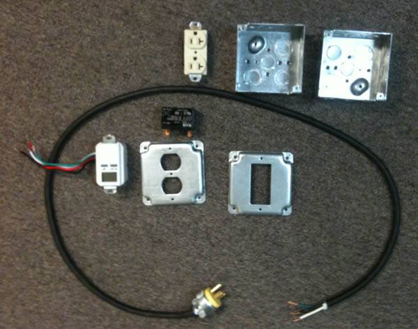
so here are the basic parts all sourced from lowes for about 50 bucks.
1 120v duplex socket
2 deep wall boxes
2 face plates w/correct cutouts.
1 in wall timer
1 30 amp 120v coil mechanical relay (10 bucks on ebay about 30 online)
12/3 cable with male connector
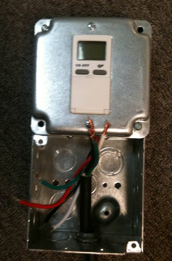
First thing we want to do the knockouts, screw the boxes together and install the timer leaving their tails in the junction box. Install power cord and strain relief. Prep all cables.
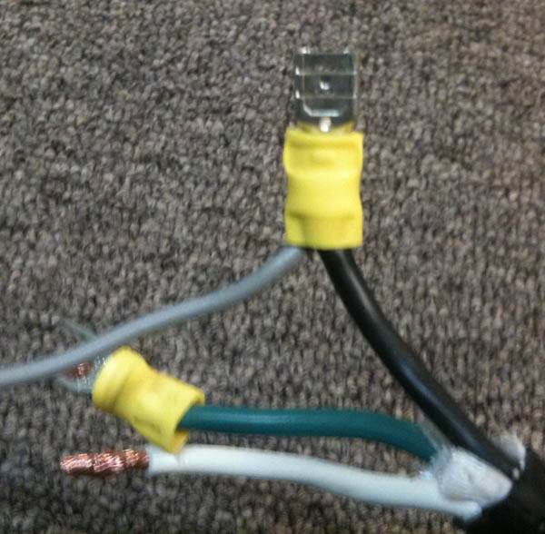
Here on our incoming HOT we have Y'd off. this connection will go to the relay and the Y will provide power to the timer.
Here we are taking the incoming neutral and connecting it to our outlet, we are able to Y off of the outlet to give the timer it's neutral as well as the neutral needed to energize the relay coil.
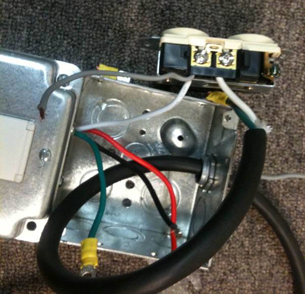
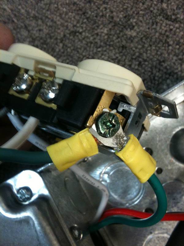
Incomming ground and timer ground are tied together at the outlet.
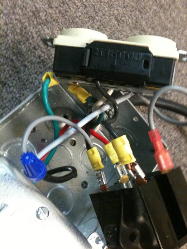
Here's where it gets a little tight. We have our hot and neutral that were Y'd off of our incoming 120V powering the timer, we also have a red lead coming out of the timer. this is our timer switched power. We connect it and the neutral to the coil inputs of our relay. Our incomming hot wire is connected to the load side of the relay and our HOT going to our outlet is connected to the other.
Here's everything put together and ready to safely switch your 15amp inductive load.
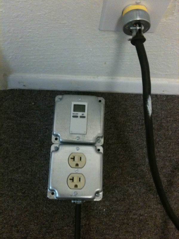
You can also wire a trigger cable to plug into into a timer instead of using a built in timer.
I will get a diagram made that will make things a little easier to follow.
A typical household timer, rated for a 15 amp load contains a small light duty relay. While on the surface, everything seems like it should be OK. the timers 15 amp rating exceeds the 9+ amps your 1k hps draws. Problem is the type rating.
There are two types of electrical loads, resistive and inductive. an HID lamp is an inductive load. the 15 amp rating on your timer represents a resistive load. Placing an inductive load on this relay, will cut it's rating by at about 50% and also drop it's MTBF (mean time between failures) drastically.
Will it work? Yes! the question is how long, and when it fails what happens?
Worst Case, start a fire, melt and short your timer and possibly take out your ballast and lamp or stick on leaving your lamps on beyond the desired time.
To solve this we use light controllers with relays and trigger cables. Great if you're running 4 lamps and 30+ amps but what if you just want to run your 600-1000 watt lamp SAFELY.
Personally, I won't run anything over a 400 on a household timer. Looking for a better timer yielded lots of expensive timers but ALL had the same crappy little relay with a fancier package.
So here's a fairly simple way to build a timer that really is rated for 15amps.
so here are the basic parts all sourced from lowes for about 50 bucks.
1 120v duplex socket
2 deep wall boxes
2 face plates w/correct cutouts.
1 in wall timer
1 30 amp 120v coil mechanical relay (10 bucks on ebay about 30 online)
12/3 cable with male connector
First thing we want to do the knockouts, screw the boxes together and install the timer leaving their tails in the junction box. Install power cord and strain relief. Prep all cables.
Here on our incoming HOT we have Y'd off. this connection will go to the relay and the Y will provide power to the timer.
Here we are taking the incoming neutral and connecting it to our outlet, we are able to Y off of the outlet to give the timer it's neutral as well as the neutral needed to energize the relay coil.
Incomming ground and timer ground are tied together at the outlet.
Here's where it gets a little tight. We have our hot and neutral that were Y'd off of our incoming 120V powering the timer, we also have a red lead coming out of the timer. this is our timer switched power. We connect it and the neutral to the coil inputs of our relay. Our incomming hot wire is connected to the load side of the relay and our HOT going to our outlet is connected to the other.
Here's everything put together and ready to safely switch your 15amp inductive load.
You can also wire a trigger cable to plug into into a timer instead of using a built in timer.
I will get a diagram made that will make things a little easier to follow.


