Since there are many, many threads with people asking how to wire this and what wire to use for that, I thought I'd make a thread to have those with some knowledge share it with those that may not have as much. Hopefully we can get this sticky so it can help people in the future.
I will start off with a couple of simple diagrams and charts (not mine ) that may help explain the very basics and hope that others will add diagrams or photos to explain things that weren't covered. I welcome anyone's input so lets get going...
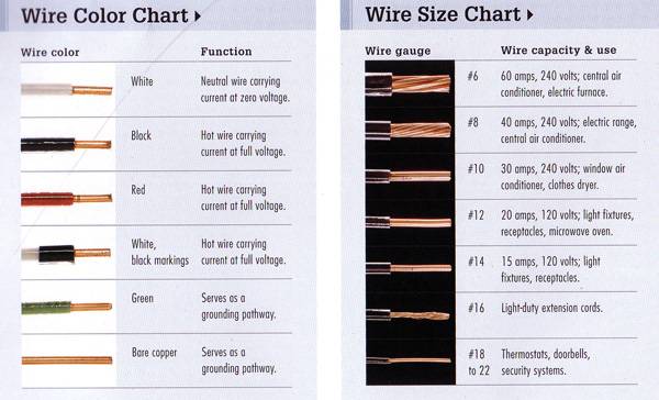
Basic wire color/wire gauge chart:

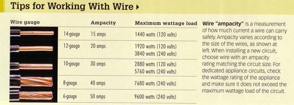
Wiring size/amperage/voltage chart:

Wiring up a basic outlet: If only one outlet per circuit follow picture to the right.

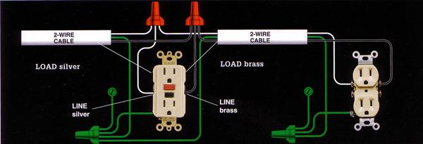
Wiring up a GFCI outlet:This shows how to wire a GFCI outlet that is NOT protecting the outlet down stream. To protect that one as well, wires going out to the next outlet would use the "LOAD" terminals of the GFCI outlet.

The green grounding screws are located within the metal outlet housing.
I hope this gets the ball rolling. Let's share what we know
I will start off with a couple of simple diagrams and charts (not mine
Basic wire color/wire gauge chart:
Wiring size/amperage/voltage chart:
Wiring up a basic outlet: If only one outlet per circuit follow picture to the right.
Wiring up a GFCI outlet:This shows how to wire a GFCI outlet that is NOT protecting the outlet down stream. To protect that one as well, wires going out to the next outlet would use the "LOAD" terminals of the GFCI outlet.
The green grounding screws are located within the metal outlet housing.
I hope this gets the ball rolling. Let's share what we know

 Re-wired it with 3 conductor cord and now it's not an issue. You should always have a ground for safety reasons anyway.
