What's new
  • As of today ICMag has his own Discord server. In this Discord server you can chat, talk with eachother, listen to music, share stories and pictures...and much more. Join now and let's grow together! Join ICMag Discord here! More details in this thread here: here.

Growroom Electricity and Wiring

madpenguin

Member
So, I have 250' of 12gauge-3 Romex (plenty) wire. The plan is to wire them to 2 x 20amp circuits.

If your going to use 12/3 wire for 2 separate 20A runs then you have to use a double pole 20A breaker. Red wire to one breaker screw and the black wire to the other.

Or, you can use 2 individual single pole 20A breakers but you would have to use 2 separate runs of 12/3 and abandon either the red or black wire in both runs (treat it like it's a 12/2 run).

From there, they will goto individual 2 x 4" x 4" metal boxes with 4 x GFCI outlets (in total). (such as one 12 guage wire to one 4" x 4" box... each having 4 places to plug in... now that I'm writing this, I will probably need another 4" x 4" box pig tailed since I need atleast 11 plugs.
O.k... I kinda wish people wouldn't run MWBC's unless they are familiar with electricity. If your going to add another 4 square into the mix (4"x4" junction box), for a total of 3, then make sure 3 duplex receptacles are fed by the red wire and the other 3 duplex receptacles are fed by the black wire.

Physically mark these receptacles with a permanent red and black marker so you know which is fed by which. Then lay out all your equipment and write down what the amperage/wattage draw is for each device. Now try to even both the red and black wires out so they are drawing approximately the same amount of power.

Wirenut ALL neutrals with pigtails. Don't daisy chain your neutral wire from receptacle to receptacle. Mechanically twist all neutral pigtails to the main neutral with linemans pliers so you have a solid twist of the wires BEFORE you wirenut it....

Bud-Boy, that applies to you as well!!!
 

Bud-Boy

Active member
Veteran
Then you'll have 2 - 20A circuits which will be a MWBC.
Please expand on that acronym

I'm not a big fan of doing that but if your going to do it, then just make sure you fuse both legs coming into the room.
Not a big fan either, but I don't have another option I can come up with, so I'll go as safe as can be

Get an AC disconnect box that takes the fuse cartridges. Put 20A ones in there and not 30 or 40 ones that may or may not come with it.Got one. But whats the difference between that and a dual 20Amp breaker box?

Make sure they wrap around each other really well, then use a blue wirenut to cap it.I was planning on crimp connectoring. is blue wirenut the weather proof?

A 12/3 run is what you would want to run into the junction box with the #10's. Just remember to even distribute the load between the red and black #12 wires and definitely fuse them.
Thanks for the confidence to get this done
 

SmokinErb

Member
Hey MP sorry to annoy you again. We did get that lease though, and are moved in by now.

I'm still stuck on the whole electrical issue with this bedroom. I know we've been over some of this but:

The room has 3 receptacles operating on 15a 120v breaker. Obviously this is not enough.

I am insistent upon kteeping the room to he NEC code.

You've already suggested old working the place, but that involves more receptacles, ect. I've been trying to find out what the NEC code for receptacle spacing is, but all I can find is "no more than 12 feet." There's no minimum distance between receptacles?

I'm considering just leaving the 15a alone and wiring up a 30a on a single receptacle that has 4 plugs. I'd use that for the lights and the 15a for everything else, but regardless of how I do it, that recepaltacle is going to be pretty close to another one depending on where I put it (and where I put it is going to be where its easiest to install)

Basically I just want to make sure I'm not about to fuck something up by putting a receptacle as close as 2 -3 feet from another one.

On the bright side, I germinated my bag seed and placed an order for some more beans! As soon as I get this figured out I'm placing an order for them HPS lights.
 

GeorgeSmiley

Remembers
Veteran
madpenguin said:
Here is a Single Pole Single Throw (SPST) Electromechanical Relay:
Relay, SPST-NO-DM, 4 Pins, 120VAC


picture.php


(BTW, Smiley, the above is the proper relay to use inline with your timer for the 120v side of your Distribution board.) There is only one "pole". It consists of the right hand metal arm and the left hand metal arm. Back some in the middle of the relay you can see one of the coil screw contacts. There is another one on the other side in the same position. This SPST relay is in a Normally Open (NO) position, meaning that when there is no electricity supplied to the center contacts, the top armature is raised and therefore does not complete the path from right contact to left contact. Once you apply current (a very nominal amount in the milliamp range) to the center contacts, the armature is magnetically energized and "snaps" down to meet both the left and right hand "arms", thus completing the circuit.

Notice the coil voltage imprinted in the lower right hand side of the relay. It says 12VDC. We want to use either 120VAC or 240VAC, depending on what we have going on. If we had a 120v coil relay, we would need a hot on one screw and then a neutral on the other side screw, thus completing the circuit and closing the armature.

Our "Always Hot" wire would be terminated to either screw. We can call this our "line in". On the other screw, you would attach the hot wire that will be feeding a 120v load. We can call that the "load out". We are feeding 120v because we only have one wire and here in N America, we have 120v on one wire.....

So my only question is, does it matter which side you hook the timed hot and neutral to? Hot on the right or left or doesn't matter?


I wholeheartedly recommend everyone get their relays at grainger. I happen to have one near and do will call but they are great about shipping. Cheapest price and these relays are Dayton not NTE, not sure if that matters.

Thanks
Smiley
 
D

Deaner

Madpenguin... what about wiring to the panel? You mentioned "terminating the ground" before connecting the hot an neutral. At what point do you reconnect the ground? I really need help on the wiring to the panel. Thanks you sooooo much.
 

madpenguin

Member
Madpenguin... what about wiring to the panel? You mentioned "terminating the ground" before connecting the hot an neutral. At what point do you reconnect the ground? I really need help on the wiring to the panel. Thanks you sooooo much.

Reconnect? Look at my sig. It's all here in this sticky. Your not reading it.... ;)
 

madpenguin

Member
Hey MP sorry to annoy you again. We did get that lease though, and are moved in by now.

I'm still stuck on the whole electrical issue with this bedroom. I know we've been over some of this but:

The room has 3 receptacles operating on 15a 120v breaker. Obviously this is not enough.

I am insistent upon kteeping the room to he NEC code.

You've already suggested old working the place, but that involves more receptacles, ect. I've been trying to find out what the NEC code for receptacle spacing is, but all I can find is "no more than 12 feet." There's no minimum distance between receptacles?

The NEC is a minimum guideline, not a maximum. You have to have a receptacle atleast every 12 feet. No more. If you want to put one every 2 feet, then go right ahead. Again, receptacle spacing is in my sig.

I'm considering just leaving the 15a alone and wiring up a 30a on a single receptacle that has 4 plugs. I'd use that for the lights and the 15a for everything else, but regardless of how I do it, that recepaltacle is going to be pretty close to another one depending on where I put it (and where I put it is going to be where its easiest to install)

Basically I just want to make sure I'm not about to fuck something up by putting a receptacle as close as 2 -3 feet from another one.

Yea... You could run a 30A circuit.

How many ballasts at what wattage and at what voltage? If you said earlier, I forget and don't feel like trying to find it again... ;)
 

madpenguin

Member
Then you'll have 2 - 20A circuits which will be a MWBC.
Please expand on that acronym

You got it. Multi Wire Branch Circuit. I've been over them tons of times. I know the thread is getting long but it's all here.

I'm not a big fan of doing that but if your going to do it, then just make sure you fuse both legs coming into the room.
Not a big fan either, but I don't have another option I can come up with, so I'll go as safe as can be
Well, there's actually nothing wrong with that plan. Just make sure all your splices are solid so you get no resistance/heat. Fuse both the #12's. Don't daisy chain the neutral. Evenly distribute the load between L1 and L2 and all will be fine

Get an AC disconnect box that takes the fuse cartridges. Put 20A ones in there and not 30 or 40 ones that may or may not come with it.Got one. But whats the difference between that and a dual 20Amp breaker box?
Nothing. The breaker box will be better because fuses you have to replace. I haven't seen a small disco box with a double pole 20A in it that I can recall so that's why I suggested the cartridge fuses. If you can get a small 20A disco then that would be bad ass. One with SP breakers will do also. Just use 12/2 after the disco and don't have both phases in one box, other wise you need to use a DP 20A breaker instead of 2 singles.

Make sure they wrap around each other really well, then use a blue wirenut to cap it.I was planning on crimp connectoring. is blue wirenut the weather proof?


Eh.... Don't crimp anything unless it's stranded. You can get a way better connection with a wire nut if it's done right. The blue wirenuts are just really big. They arent weather proof.
 

SmokinErb

Member
We haven't purchased any lights yet. But I'm trying to wire it to accommodate 2kw HPS on a flip box. The room only has a 15 amp circuit already in place, I wouldn't want to go over 1kw on that 15 amp circuit, so I figure 30 amps for the 2kw on one receptacle dedicated to the ballasts, and the other 15 amps for the veg lights, fans, and possibly a 5k btu window ac if needed. Voltage will be 120.

I'm going over the first few pages trying to get a list of everything I need, and so I got a question regarding the wire. I'm basically positive that I need 10/3 romex for that 30 amp, but on the first couple pages I see a lot of 2 wire cable mentioned as well as "2 wire with ground" cable. Isn't 2 wire cable a bad idea for running ballasts? And isn't 2 wire w/ ground the same as 3 wire?

Edit: After doing some more reading, I figure I ought to just go with a 20a breaker. If I'm only running 2kw on it, it shouldn't be a problem. I was just going by the chart on page 1, where the 20a says the max watts are in the 1950w range (can't remember). I opted to go for the 30 because I wanted to be on the safe side, but doing the w/v=a equation 2kw is only 16-17 amps. Don't see why I shouldn't be able to dedicate a single 20a circuit for the ballasts.

Also, with flip boxes, do you need to use a timer? I mean since the ballast is now running 24/7, doesn't that pretty much eliminate the need for one? So if I was running 2 ballasts, I could just use a standard receptical since I can just plug them directly into the wall instead of on a bulky timer. So I'd save money on ballasts, timers, and heavier gauge wiring this way.
 

Bud-Boy

Active member
Veteran
Thanks Again MP!
It all fired up without a problem. Im happy with all the work too. Nothing was compromised. I am only running on half that tap for now. Everything feels cool.
Posted a Note on the dryer for non-operational hours :D

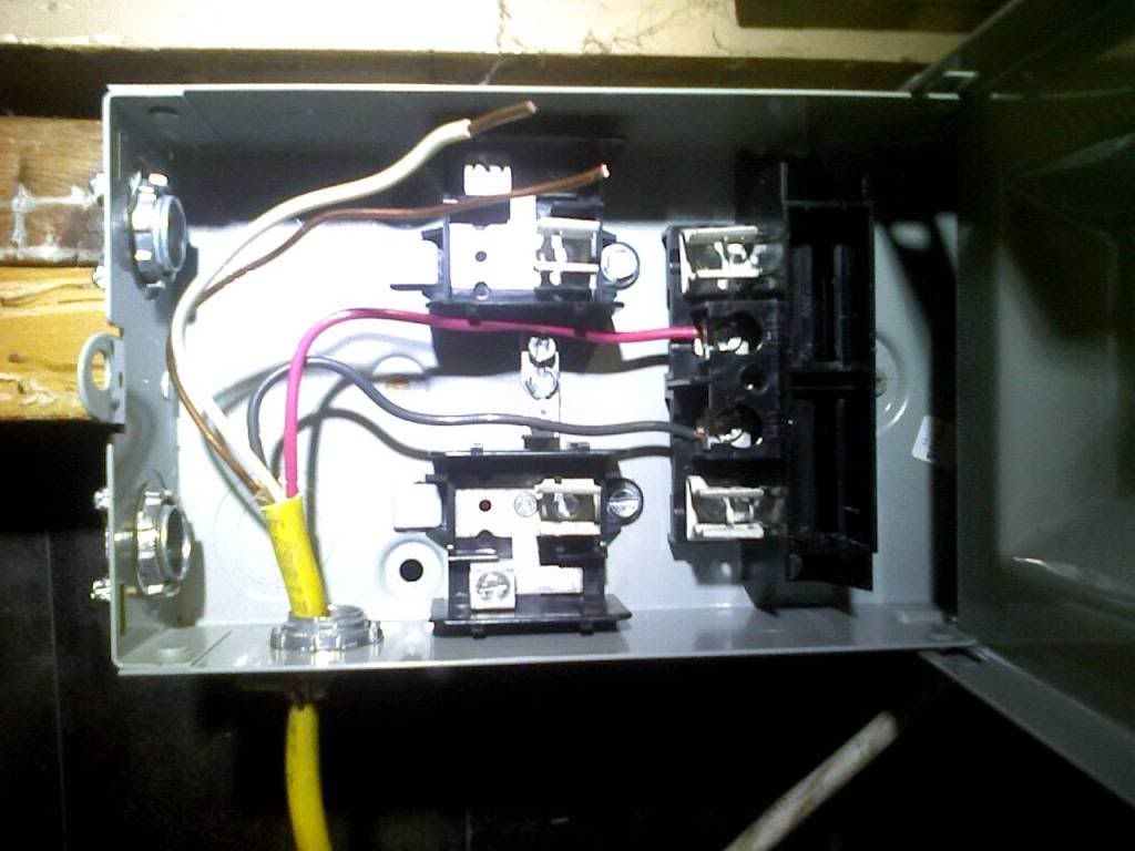
The disconnect box only has two grounded lugs to connect to.
What's the recommended way to approach this?

Get a different lug terminal that has enough slots for wires?

Does ground and Neutral need to be separated? Is there a rule for remembering when this needs to be done?

PIC-0184.jpg
 

madpenguin

Member
Thanks Again MP!
It all fired up without a problem. Im happy with all the work too. Nothing was compromised. I am only running on half that tap for now. Everything feels cool.
Posted a Note on the dryer for non-operational hours :D

Good idea about the note. BTW, once you start using the other leg, the return current on the neutral will drop to carry the imbalance of the load between L1 and L2. Just a FYI incase you didn't read about MWBC's yet in this thread.

The disconnect box only has two grounded lugs to connect to.
What's the recommended way to approach this?

You can do one of two things. Connect the bare #10 to one lug and then connect a #10 pigtail to the other one that gets you back towards the 2 NM connectors you have installed. Then when you go to run your 2 separate 12/2's, just wirenut all the grounds onto that pigtail.

That or you can go buy a 3-5 slot ground bar kit and fasten it directly to the frame of the panel. Probably right between those 2 NM connectors would be ideal. Still terminate the main feeder ground to the center one. Still make a #10 pigtail to go from the center one to the new one you install, and then terminate your 12/2 grounds to the new ground bar.

That's probably how I would do it just because it would look neater. Other than that.... It doesn't matter.

Does ground and Neutral need to be separated? Is there a rule for remembering when this needs to be done?

Yes. They need to be separated. The only time neutrals and grounds should be bonded together is at the enclosure that holds your first disconnecting means. That would either be your main panel or an outside disconnect by the meters. If you start at your meter and work your way in to the house, the VERY FIRST DISCONNECT is where the grounds and neutrals need to be bonded together. After that, they always stay separated.

So.... That being the case, you'll need to wirenut all your neutrals together in that enclosure and keep them away from the grounds.

PIC-0184.jpg


Looks good. That's the perfect thing to use. Slap some 20A cartridges in there and your good to go.
 

SmokinErb

Member
Okay so I talked to the guy @ Lowes about it, and I think I actually got a better understanding of how simple this really is.

I'm gonna grab a 20a breaker, 12/2 romex, old work box, and the receptacle. That comes out to like 30 bucks?

$15 for 25' of 12/2
$2 for old work box
$3 for 20a rated receptacle
Breaker should be under $10.

I'm assuming this is basically everything I need minus the $40 drill bit anyway? Except for the drill bit, this is far less expensive than I originally thought it was going to be - that's always good news! I'll be getting around to doing all the work this week.

I gotta ask though, how do I go about getting a timer for a relay? I've always used the brinks timers from walmart that are like $15, here's what it says on the back:

Rating 120Vac, 60 Hz, 15A Resistive, 500W Tungsten, 1/3 HP.

Not gonna cut it, huh?
 

RipVanWeed

Member
Much Respect Madpenguin,

Were you Phillthy?

I was hoping to get some electrical help. I'm pretty comfortable with the mechanical installation, but I need help with sizing of wires and breakers.

Going to add a subpanel for a new growroom I built in my garage. I previously ran a branch circuit to this area using 10/3 armorclad. It's about a 35' run from the mainpanel to where the subpanel will go.
I have a list of equipment that will be running in the room, these figures have been inflated for future maxamization of the room (I may have gone overboard on this).

6 x 1kw HPS
2 x 400w MH
6 x 20" box fans 40w each?
10 x airpumps 8w each
3 x 6" vortex 110w each
1 x 10" vortex
1 x cloner water pump 35w

All ballasts are switchable, so at least all the 1k's should be 240v.

I'm going to go take some pics of where I'm at right now.

Thanks in advance,
 

RipVanWeed

Member
This is the crate I used to use as a grow area


Built a 11' x 12' room around the crate ...9' ceilings!


Let me know what info I can get you for the best answers.

Much Respect,
 

madpenguin

Member
I'm going over the first few pages trying to get a list of everything I need, and so I got a question regarding the wire. I'm basically positive that I need 10/3 romex for that 30 amp, but on the first couple pages I see a lot of 2 wire cable mentioned as well as "2 wire with ground" cable. Isn't 2 wire cable a bad idea for running ballasts? And isn't 2 wire w/ ground the same as 3 wire?

Romex and flexible/extension cords have a different lingo when you talk about them. With romex a 12/2 has 3 conductors. You don't count the ground. So a 12/2 romex cable is actually a black, white and bare ground. 3 conductors.

When you go shopping for an extension cord, you'll come across 12/3... It's a black, white and ground. The same thing as 12/2 romex only they are counting the ground.


Edit: After doing some more reading, I figure I ought to just go with a 20a breaker. If I'm only running 2kw on it, it shouldn't be a problem. I was just going by the chart on page 1, where the 20a says the max watts are in the 1950w range (can't remember). I opted to go for the 30 because I wanted to be on the safe side, but doing the w/v=a equation 2kw is only 16-17 amps. Don't see why I shouldn't be able to dedicate a single 20a circuit for the ballasts.
Dude. Ohms law is just a rough estimate. Don't use it. Look at the name plate on your ballast. If it doesn't haven't a metal nameplate on it, then find a PDF on your specific ballast. Falling that, use an ammeter on the hot wire. Either way you slice it, you need an exact amp rating that your ballasts draw. Ohms law will not get you there.

16 Amps is the maximum you can draw on a 20A circuit with continuous loads. 16.1 Amps and you need to bump up to a 30A breaker with #10 wire. Don't fuck around with that. I mean, ultimately, it's up to you. If your drawing 17A and want to use #12 and a 20A breaker than go ahead, but I wouldn't.

Also, with flip boxes, do you need to use a timer? I mean since the ballast is now running 24/7, doesn't that pretty much eliminate the need for one? So if I was running 2 ballasts, I could just use a standard receptical since I can just plug them directly into the wall instead of on a bulky timer. So I'd save money on ballasts, timers, and heavier gauge wiring this way.

I think your not fully grasping the concept of a flip/flop. 2 ballast that run 4 reflectors (but not at the same time). Yes, the 2 ballasts run 24/7 but without a timer to flip the relay contacts, how are the other 2 reflectors ever going to fire up? Do some research about flip/flops here on Icmag.
 

madpenguin

Member
I gotta ask though, how do I go about getting a timer for a relay? I've always used the brinks timers from walmart that are like $15, here's what it says on the back:

Rating 120Vac, 60 Hz, 15A Resistive, 500W Tungsten, 1/3 HP.

Not gonna cut it, huh?

Any timer will work. All the timer will be doing is closing the armature of the relay to join the contacts. That uses milliamps worth of current. The shittiest timer you could possibly find would work with a flip. The relay does all the heavy lifting, not the timer.
 

madpenguin

Member
Much Respect Madpenguin,

Were you Phillthy?

Nope. He's still floating around here somewhere. I've kinda had this thread thrust upon me as it were.... :bump:

I was hoping to get some electrical help. I'm pretty comfortable with the mechanical installation, but I need help with sizing of wires and breakers.

Going to add a subpanel for a new growroom I built in my garage. I previously ran a branch circuit to this area using 10/3 armorclad. It's about a 35' run from the mainpanel to where the subpanel will go.
I have a list of equipment that will be running in the room, these figures have been inflated for future maxamization of the room (I may have gone overboard on this).

6 x 1kw HPS
2 x 400w MH
6 x 20" box fans 40w each?
10 x airpumps 8w each
3 x 6" vortex 110w each
1 x 10" vortex
1 x cloner water pump 35w

All ballasts are switchable, so at least all the 1k's should be 240v.

I'm going to go take some pics of where I'm at right now.

Thanks in advance,
O.K... Not entirely sure what the question is . That 30A isn't going to cut it tho. You can easily use Ohms law for a rough estimate of what your power requirements will be.
 

Latest posts

Latest posts

Top