Hello,
I am currently running a light controller identical to this one except I have an in-wall digital timer controlling the main 30A relay:
https://www.icmag.com/ic/showthread.php?t=301017
I am anal and want to take safety to the next level. I want to add a current sensing relay with time delay in order to shut off my light in the event my fan stops working. It will also add a time delay in the event of power outages to prevent hot re-strikes since my ballast lacks that feature.
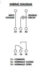
I have this CS relay: http://magnecraft.thomasnet.com/item/all-categories/820/pn-2927
According to what I have read, when talking about relays, the "common (c)" connection is not a neutral wire, but a hot wire. Going off that, I plan to wire to switched load output of the wall timer to the "common" (c)" on the CS relay, then from there to the control wire of the main 30A relay.
The idea is that under normal operation, the CS relay will sense current from the fan being on, and will be in a closed circuit state, passing the wall timer's switched load to the main 30A relay. This way the wall timer is what will control the lights turning on and off.
In the event of a fan failure, the CS relay will no longer sense current and flip it self into a open circuit, cutting off the signal from the wall timer, and turning off the lights. Then no matter what the wall timer is doing, the CS relay will be blocking the signal from it, keeping the lights OFF.
In the event of a power failure during normal, the CS relay will sense current again from the fan, but instead will delay flipping to a closed circuit, preventing a hot re-strike.
Does that sound right? ANY help or advice is greatly appreciated. Thanks!


