What's new
  • As of today ICMag has his own Discord server. In this Discord server you can chat, talk with eachother, listen to music, share stories and pictures...and much more. Join now and let's grow together! Join ICMag Discord here! More details in this thread here: here.

PL-L wiring socket and overdrive help

monarch

Member
Need some help with wiring on a dual PL-L led fixture.


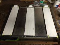
Im wiring 165w of PL-L right now and need some help, the lights will sit under reflectors where the white currently is. COB led's will be on the heat sink, but thats for another day.

Im using a Fulham Workhorse 8 ballast to 3x 55w lights. All wire is 18 gauge.

Here is Fulhams wiring diagram for 3x 55w twin tube ligts.


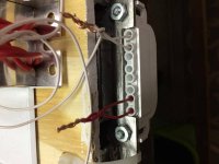
And here is my socket. The white is the neutral yellow a going to the ballast and the red is the hot. I understand the neutral circuit but not the red. Fulham shows combining 2 hot wires coming out of the ballast to one light. There are 6 red wires, 2 per light. This as I understand is overdriving the light? Can I connect the two ballast wires directly to the two entering the socket pin? the wiring diagram says to "combine" before wiring to the socket. Am I supposed to wire them together first or will all four (two ballast , two socket) wires link up fine under one wire nut or connection all together?


Im also having trouble with the socket wiring. Not sure if I need a jumper or not and if my leads are correct. here is the product.

I have been through ALL the pl-l threads and can't seem to find a 100% answer on a 3 x 55w set-up with dual red wires (overdrive?) coming from the ballast and my sockets specifically. Don't want to burn my house down.

thanks
 

Attachments

  • IMG_0751.jpg
    IMG_0751.jpg
    48.4 KB · Views: 13
  • IMG_0701.jpg
    IMG_0701.jpg
    51.4 KB · Views: 12

queequeg152

Active member
Veteran
there are usually two terminals for each pin on the light fixture. this is so you can jump a wire from the same terminal to the next terminal or next light. so 4 pins = 8 terminals.

i run my p ll fixture on a workhorse 8 and i dont recall having to run two wires to each lamp? i dont get that.
pretty sure i capped off like 4 of the unused red wires and just jumped the socket terminals.


ive never overdriven anything... but from what i recall its basically running another circuit into the bulb pins instead of jumping a single circuit over to the other lamp pin.

this does indeed look like an overdrive wiring scheme, but perhaps not.
this might be a 2 stage ballast or perhaps some sort of fancy rapid start thing, whereby one line is pushing out the high voltage high frequency for the lamp start, then the other one cuts in with the running voltage? idk just a guess, not real sure...

whats the model number? im curious to read about it.
 

queequeg152

Active member
Veteran
err, i just saw you and i have the same ballast.

ok so i just went to the website and checked... i guess im running an unapproved lamp combo? im running 4x 55watt osrams wired as per wiring diagram 27. ive been running this for years and years... 2011 actually.

http://www.fulham.com/WDpdf/wire27.pdf

im havine to relamp every 2 or so years as they seem to dim loosing like 10% or more output at room temps as read from my cheap as shit lux meter.
i wonder if the unapproved lamp combo is the reason why.

when i relamp i leave like 2 old ones in and don a pair of sunglasses... the new verses old lamps output is distinct.

thinking about rewiring now...
 

monarch

Member
quee,
I was originally going to go with 4 x 55w but saw that the manufactures spec changed. From what I read it is okay to run 4 x 55w on a workhorse 8. A lot of people (including yourself) were doing it before and even long after they changed the specs. It was discussed a little in this thread

**note: thats not the correct page but the conversation is somewhere after that I believe. Maybe around page 50?. Sorry i don't feel like digging it up again. lol

But the consensus is that its safe to run 4x55w. Fulham changed it for a few reason, I believe reliability might have been one. I think for growing applications where you are only turning the ballast off and on once a day, not at will with a light switch, makes it practical for the ballast to handle. I think they also noticed reduced life on the 4 bulb setup, which correlates to your experience.

Back to the wiring. The diagram deff shows two red leads for each bulb. I know I can use one red wire per bulb, cap the rest, and be done with it but I would like to get the most out intensity I can out of my bulbs. Im confused on were they say combine the two before connecting to socket. Is it okay to have all four twisted together? 2 red wires from the ballast hooked up to 2 red wires on my socket like I have?

And how did you jump yours? the diagram shows jumping the circuit for a linear bulb but not a twin stlye pl-l.
 

queequeg152

Active member
Veteran
quee,
I was originally going to go with 4 x 55w but saw that the manufactures spec changed. From what I read it is okay to run 4 x 55w on a workhorse 8. A lot of people (including yourself) were doing it before and even long after they changed the specs. It was discussed a little in this thread

**note: thats not the correct page but the conversation is somewhere after that I believe. Maybe around page 50?. Sorry i don't feel like digging it up again. lol

But the consensus is that its safe to run 4x55w. Fulham changed it for a few reason, I believe reliability might have been one. I think for growing applications where you are only turning the ballast off and on once a day, not at will with a light switch, makes it practical for the ballast to handle. I think they also noticed reduced life on the 4 bulb setup, which correlates to your experience.

Back to the wiring. The diagram deff shows two red leads for each bulb. I know I can use one red wire per bulb, cap the rest, and be done with it but I would like to get the most out intensity I can out of my bulbs. Im confused on were they say combine the two before connecting to socket. Is it okay to have all four twisted together? 2 red wires from the ballast hooked up to 2 red wires on my socket like I have?

And how did you jump yours? the diagram shows jumping the circuit for a linear bulb but not a twin stlye pl-l.

thanks for that info... makes me feel better, considering it might have been approved back when i put that lamp together. i still might go out and look for a good programmed start ballst with a proper rating... but idk, its spring and all my transplants are outside and the fixture is done for the year.

to be clear im not into electronics in general. i can wire shit... panels, control systems, sensors and shit like that, but i cant BUILD electronics or anything. i dont even really understand most circuit schematics unless they are dumbed down hvac wiring diagram style or down to simple ladder diagrams. RCS circuits and ocillators ... thats as far as we went in school, and i hated that shit.

but ill gladly share what my... general overarching understandings are on these ballasts.

regarding the wiring, i think you are just going to have to fire off an email or call someone to be 100% sure? if it were me id wire it both ways and see wtf the difference was. these ballasts come with like 400 feet of wire... whenever i replace shitty ballasts i always end up cutting off like 90% of it and shoving it into my solid core scrap wire box thing.

yea the workhorse 8 is an instant start... which isnt great for lamp life... technically for all of these bulbs you want a programmed start, but what ever. it was alot cheaper than a proper ballast way back when i bought it. the ballast factor seemed good for the 60 bucks or what ever i was charged.

it sure looks like an overdriven setup to me... but its important to remember that these all digital ballasts do all sorts of self regulating shit that old magnetic ones did not. i think they can actually adjust to each lamps individual issues... resistance or impedance shit like that. i think they can also sense current and limit accordingly. i know they can sense faults in bulbs.

i went back and looked at my ballast wiring last night. i jumped it via a wire junction, NOT a jumper from one to the other. i wired a Y shape basically if that makes sense... i guess i can post a pic if you want? but its basically the exact same as the 27 wiring diagram.

supposedly the y shape is more reliable because if, for some some reason the wire feeding into the socket is loose or cracked or the clamp in the socket itself is damaged in some way , the jumped wire then cannot send power to the other side of the starter coil thing either.

because remember that these instant start ballsts do not preheat anything, they just work like the old school t12 bulbs with one bit nipple sized pin on each end. the coils act as cathode and annode and they just get raped by a high voltage high frequency blast that gets the gasses and shit excited and ionized.

since they dont preheat, they can start a bulb by just pumping current to only one side of that fucking liittle coil thing inside there. given this... the Y shape ensures you have the maximum chance to light the bulb when 1 of the 2 wires is fucked.

Im confused on were they say combine the two before connecting to socket. Is it okay to have all four twisted together? 2 red wires from the ballast hooked up to 2 red wires on my socket like I have?

ok so given the above... assuming im correct in all that bullshit, i think it stands to reason that combining the two wires, then splitting them again makes sense no? you are joining the two lines together to (probably) over drive the bulb, then splitting them into a wye for the reliability reasons i mentioned above.

yes you would wire nut the two red wires from the ballast to the two from the socket. just be sure you buy wire nuts that are rated for 4 18 gauge wires. wire nuts are sketchy for alot of reasons, so make sure you are using the proper ones. ballast wire is sometimes very brittle so be careful to not over tighten. might not be a bad idea to back a bit of dielectric grease into the bottoms of the nuts if this thing could possibly get wet.

anyway,the yellow nuts are good for like... 3 14 gauge, 2- 12 gauge, and thats all i know. you will have to look at the box or bag for details on that one.

the red nuts are good for like 4 12 gauge and a shit load of 14 gauge wires... the ones bigger than that... i think they are blue are basically pig tail nuts, what for joining a shit load of commons in some huge 6 gang boxes or what ever. they are enormous. bigger than my thumb you need lineman's to twist those shitty things.

the tiny tiny wire nuts are for shit like doorbell wire, dont use those they are not reated for real currents. i think you will end up needing a bag of the yellow nuts, but just double check.
 

monarch

Member
Thanks for the info on the wire nuts. I will probably actually use a different connection like the male/female connectors you get from harbor freight and insulate them. I just wanted to know if hooking all of them under one "connection" was legit.

I thought about just trying to wire it up a bunch of ways and see what works like you said, however I am hesitant not to destroy any electronics I just purchased. Im afraid I'll burn something out.
 

queequeg152

Active member
Veteran
i reccomend against cheap ass connectors. ive gone through my fair share... and they are not that much cheaper than real 3m skotchlock connectors.

the harborfrieght shit isnt legit tested and rated... and thats about it. ive never had one fail, but still i prefer to go with the 3m stuff for peace of mind. they are not that much more expensive.

you want either a 4 way butt lock or a 2x2 splice, 3m makes both. check out their skotchlock catalogue and then go on amazon and buy a small bag. make sure to get stuff rated for real current... not low voltage shit. make sure its rated for your wire gauge too. this info is all inside the catalogue.

just went througg like 50 of these for low votlage lighting around my houses vinyl soffits.
 

Latest posts

Latest posts

Top