What's new
  • As of today ICMag has his own Discord server. In this Discord server you can chat, talk with eachother, listen to music, share stories and pictures...and much more. Join now and let's grow together! Join ICMag Discord here! More details in this thread here: here.

Distributed passive intakes in Vert/Replace fans

OG_TGR

Member
So I am setting up a new Vert and I was thinking about creating intakes where the small Honeywell fans would go. In theory I believe this could possibly allow me to eliminate the fans and associated power draw, as well as the obstacle of having to route cords. I know the power draw is minimal but every little bit counts; it takes many 1s and 2s to make 10s, 20s and 100s!
I have 4 lights hanging in a 621'^3 space (9' x 11.5' x 6'h) with a 440cfm inline Vortex exhaust fan. By my calculations this should distribute ~60cfm to 4 x 4" holes.
I came by this number by taking the area of the 6" exhaust (28.3in²) against the combined area of 4 x 4" holes (50.3in²). Since the total area of the passive intakes is roughly 34% larger than the exhaust I took 56% of the exhaust fan rating/4.

I'm going to try it regardless but; I wondered if anyone had further thoughts on this idea?[FONT=Arial, Helvetica, sans-serif]"[/FONT]
 

OG_TGR

Member
While looking at parts today I decided to install the intakes with 3" reducers. In theory, this will increase the velocity without changing the volume noticeably. I am going to take temperature measurements with and without to see if there is a difference.
 

RonSmooth

Member
Veteran
While looking at parts today I decided to install the intakes with 3" reducers. In theory, this will increase the velocity without changing the volume noticeably. I am going to take temperature measurements with and without to see if there is a difference.


I dont think reducers are a good way of increasing efficiency. Seems they would only make the fan work harder to draw less air.

Not sure if I am following your calculations. The intake calculation refers to the air being drawn into he room not the fan itself. The more splitters, ducting and reducers you have, the more the CFM rating of the fan decreases.

If I had a 6" fan exhausting air from a 6'x6'x8' room, there must be sufficient air entering the room for the exhaust to work properly. So I would need to install intake ports at least twice the area of the exhaust.

Maybe I misunderstood.

This time of year is tough. I am dealing with temp/humidity issues as well.
 

OG_TGR

Member
I dont think reducers are a good way of increasing efficiency. Seems they would only make the fan work harder to draw less air.

Not sure if I am following your calculations. The intake calculation refers to the air being drawn into he room not the fan itself. The more splitters, ducting and reducers you have, the more the CFM rating of the fan decreases.

If I had a 6" fan exhausting air from a 6'x6'x8' room, there must be sufficient air entering the room for the exhaust to work properly. So I would need to install intake ports at least twice the area of the exhaust.

Maybe I misunderstood.

This time of year is tough. I am dealing with temp/humidity issues as well.
Well, my thoughts are that the inline, centrifugal fan is pretty linear as far as operational fluctuations. I have tested the draw on the fan as I have gone through and closed old configuration holes and it is still running at or very near rated cap. Once I get the new intakes in, I will test the fan operation again to make sure it isn't backing up. The envelope of my area is very tight. I've used an advanced commercial vapor barrier and have almost absolute control over any infiltration throughout. With the 4" holes I have almost double the intake area as exhaust, and I wouldn't want to go much more over that, in order to maintain a good negative pressure.
With 4x3" I would be ~16% smaller intake that exhaust, and that is something I may have to address. The thing is, I would expect that with a linear fan, the decrease in intake diameter will likely not decrease the volume much but rather increased the velocity of the air coming in. Now of course this may not work like I want it to because if the air is moving too fast, there isn't time for it to pick up heat and therefore it doesn't cool the bulbs sufficiently.

Without doing anemometric calculations and taking specific point temperature readings, I think I can determine which will do the best in the long run. I am currently doing a "dry run" to see what the temps will end up like with no floor intakes and only one high placed intake. I plan on blocking this off and using just the floor intakes, and compare it to this baseline.

I have high expectations for the floor vents, we'll see!

Overall my temps and RH have been good last run, never more that 80-81. I have a dehumidifier outside the room that dries the intake air.
 

OG_TGR

Member
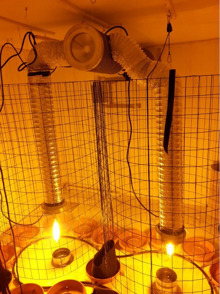
Heat was WAAY too high for 4 bulbs and only a 4xxcfm 6" fan. Although, the floor intakes seem to be doing the job (more or less) with 2 bulbs and 2x6" intakes, plus another ambient 6" intake. Temps are still a little higher than I'd like to so tomorrow I am switching out with 10" fan/ducting, and before I run the other two lights I plan on switching to a mixed-flow, 1260cfm fan. Instead of 4 individual screens I decided to just go with two, stacked.

11_zps26d77d38.jpg


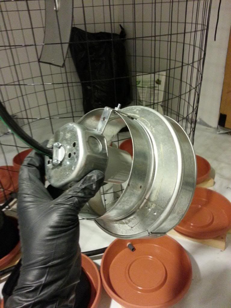
Intake construction:
22_zps592043fa.jpg
 
Last edited:

OG_TGR

Member
Slick experiment... I'll keep watching.:lurk:
Thanks man.

The biggest drawback, that I took into consideration from the very beginning, is that if the door is open, there is very little flowing through the vents.
If I think eventually, maybe next time around, I may actually duct these in from the sides, as opposed to from the bottom. Given that there is only 3.5" of clearance under the floor, ducting could make the flow much less turbulent and possibly be more efficient.

I started out @ 97.8°f and I'm now down to 87.5°f so I'm on the right track!
 

danielJackson

New member
Cool idea, I've been thinking of something similar as well. I am particularly intrigued by your idea of reducing the intake size at the end of the line to increase velocity.

If you want to cool your room without A/C, and if is colder outside then your room. You can guestimate the cooling effect of your air exchange using the following formula;

(3.2 x Wattage of Lights in Room) / (Grow Room Target Temp - Intake air temp)

This will equal the CFM needed to cool a room with outside air and a passive intake.

Remember, size your intake based on exhaust CFM, not exhaust size!! About 1 square foot is required for every 300 CFM.

I check out your grow in your sig; if that is what you are working with here is my guess as an example

3.2 X 2400 = 7680 / 15 [(80 (Target temp) - 65 (A guess at your intake air temp))]

512 CFM required (after all reductions due to ducting and filter etc.). Still less then one exchange per minute. You can see how a cool outside temp can really help if you have a fan big enough to take advantage of it.

Divide by 300 for intake size, and spread it out to maximize your air columns over your bulbs.

It would be interesting to make your holes under the bulbs the same size as a large shop vac hose. Then you could use a cone attachment or something to really try and shoot the air.
 

OG_TGR

Member
Cool idea, I've been thinking of something similar as well. I am particularly intrigued by your idea of reducing the intake size at the end of the line to increase velocity.

If you want to cool your room without A/C, and if is colder outside then your room. You can guestimate the cooling effect of your air exchange using the following formula;

(3.2 x Wattage of Lights in Room) / (Grow Room Target Temp - Intake air temp)

This will equal the CFM needed to cool a room with outside air and a passive intake.

Remember, size your intake based on exhaust CFM, not exhaust size!! About 1 square foot is required for every 300 CFM.

I check out your grow in your sig; if that is what you are working with here is my guess as an example

3.2 X 2400 = 7680 / 15 [(80 (Target temp) - 65 (A guess at your intake air temp))]

512 CFM required (after all reductions due to ducting and filter etc.). Still less then one exchange per minute. You can see how a cool outside temp can really help if you have a fan big enough to take advantage of it.

Divide by 300 for intake size, and spread it out to maximize your air columns over your bulbs.

It would be interesting to make your holes under the bulbs the same size as a large shop vac hose. Then you could use a cone attachment or something to really try and shoot the air.

Excellent information! Can you tie a specific thermodynaic principle to that formula? I'm just curious where the 3.2 comes from, specifically. If only my outside temps were 65°!! I am currently working with something more in the 70-76° range, worst case scenario.

I haven't tried increasing the velocity, yet. At the moment I'm a bit concerned with decreasing my overall passive intake capacity, while still maintaining some degree of negative pressure. If I increase my overall intake area based on cfm, do you think the concept of increasing velocity at this point could make a difference?
I ended up putting 6" intakes under the lights, as those were the starting collars I had available within arms reach, haha. I seem to be getting decent flow through them but I am concerned about how much volume is really coming through there, and how laminar (undisturbed) the flow is. I've constructed some additional 3" collars or cones to go on the light intakes out of the flashing I had originally draped over the filter. I don't expect this to make a huge difference in capturing the heat but; if I can ever get an undisturbed baseline reading I can tell if minor modifications are making a difference.

43E043A0440044304360430044E04490430044F044104400435043404300_zps7a033bb4.jpg


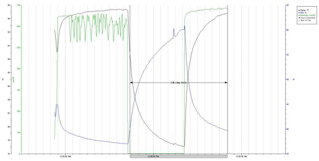
This are my readings from last night. As you can see it got pretty hot, pretty fast; with the greatest climb coming in the first 60 minutes or so. I have taken into consideration that I did have an intake come off and I assume it was somewhere around 1am. This would only make a small difference but still, it's not a absolutely accurate temperature profile.

Wow so I just did some calculations and that formula does really tie in to the results that I have been seeing thus far. I am going to recalculate my current intake size area and see if I can make some changes there.

I also calculated that my current blower COULD be sufficient, if my outdoor temps were consistently under 62°f, lol.

Thanks a million!
 
Last edited:

danielJackson

New member
I don't know how that formula is derived, but I would like to know. I think I originally read it in the Ventilation 101 thread. The 3.2 is the number I'm curious about.

I have a smaller area and was thinking of using 4 inch rigid water pipe for the intake tubes, with some kind of manifold from an oversized duct.

It would be cool to build a raised flood with a drain and ventilation all build in.
 

danielJackson

New member
Oh I forgot, I noticed your ducts from you light look like they are just taped to the outside of your scrubber. In the past I have stuck my scrubber in a big rubbermaid and cut holes in it for the ducts, basically making it an inline. This worked pretty well for me.
 

OG_TGR

Member
Ah yeah, that is a great idea about the rubbermiad, I think I have seen something like that before. Well, I am going to have to get another scrubber anyway so I might as well quite messing around and get a stealth box or make something similar. I really like them not only because of control aspects but also due to the fact that there is less bulk to throw away and be wasted, when it comes time to replace filters.

So far today it appears that putting all the vents/ducts in proper place did help but, in the end, is only prolonging the inevitable. So far today my high temp is within .5°f of yesterdays high, but still almost 10hrs (/16) off of when that peaked.
Calculating by the 1ft^2/300cfm; I had >43% of the area of intake I should have. Just now I opened up another 6" that I had blocked off, which puts me somewhere around 57%. I'm curious if this makes any difference in readings tomorrow, but I know I still need to create more intake area.

43E043A0440044304360430044E04490430044F044104400435043404300i_zpsa5e33b53.jpg
 

danielJackson

New member
I've used the stealth box and the inline phresh filter. Both work well. the stealth is not available around my area anymore, but I like the replaceable filter cartridges. I am a little confused as to how long the last. Read this;

"Technical Specifications
The heavy-duty Air Box 4 will successfully eliminates odors for up to 18 months
Carbon filter should be changed often; please replace filters every 3 month (all of them) for better results"

I might be interesting to try and make your own cabinet to hold their filters, maybe right up with intakes for each of your lights.
 

OG_TGR

Member
I've used the stealth box and the inline phresh filter. Both work well. the stealth is not available around my area anymore, but I like the replaceable filter cartridges. I am a little confused as to how long the last. Read this;

"Technical Specifications
The heavy-duty Air Box 4 will successfully eliminates odors for up to 18 months
Carbon filter should be changed often; please replace filters every 3 month (all of them) for better results"

I might be interesting to try and make your own cabinet to hold their filters, maybe right up with intakes for each of your lights.
Yeah that description on the Stealth site always gave me the willies (lol) but, I have used them and it worked quite well, for some time. The refill cartridges are super expensive, for what they are. There are other options that aren't made for this particular market (rather, new construction, high end homes), that are much more reasonable and just as effective. I wouldn't mind fabricating something completely custom but I just don't have the time for the R&D right now. I'm currently so far behind schedule that I just need to implement a solution asap and get rolling. Definitely something I can consider for next summer, though.

the room looks sick. is the black tubing to bottom feed or let the runoff escape?
Thanks man! The tubing you see now is actually drainage. I am going to layer the bottoms of those saucers with Hydrocorn, and top feed with 2 spaghetti lines/site.
 

danielJackson

New member
Cool, I never had a problem with my stealth box either, and at the time it was the only inline around. I think I ended up replacing the cartridges once just because it seemed like a good idea, never smelled anything.

Have you found any cartridges that seem to have densely packed activated carbon like the air box product?
 

OG_TGR

Member
I used one years ago and it was great. Just never got another b/c there is always a pile of standard carbon filters right there whenever I needed one. I remember that I got my replacement cartridges from a lab supply place, or possibly Grainger. If you have the dimensions correct there are lab/commercial grade replacements to be had for somewhat of a discount, but not a huge difference.
My new fan should be here by Wednesday next week, and I will likely put a regular carbon filter on it, for convenience. I'd really like to have another Stealth box but can't handle the turnaround time right now.
 

OG_TGR

Member
Cancelled my order for the 10" from the local place and got a 12" 2100cfm mixed flow fan for less than what they were going to charge me for the 10". Should still be here by the end of the week. I'll post my results/findings, as well as this weeks readings after cutting more intakes.
 

OG_TGR

Member
Started to run the new ductwork and then shit happened, lol. Nothing major but I am again delayed until tomorrow.
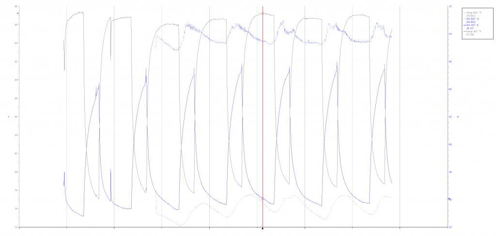
I've got some int/ext readings now to compare and what I've found is very promising, I feel.
Basically my average highs are very high right now, still. I can't say whether the floor intakes have made much difference at all, just as much as I can't say if the overall temps wouldn't likely be lower at this point [likely], had I made more intakes. I didn't see any noticeable drop in temps since I opened the additional 6" duct the other day but, I did see that at my maximum temperatures [see cross-hair], there was a ΔT 20.5° and ΔRH 28.5%. This is very promising to me because it says that, with appropriate ventilation, favorable temperatures can easily be achieved.

Currently I am looking at:

EXT: Max 78 Min 74 Avg 76
RH: Max 73 Min 74 Avg 76

INT: Max 97 Min 77 Avg 91
RH: Max 65 Min 37 Avg 46

I am curious though, how this [high ventilation] is going to effect RH; but I don't foresee it being a big issue.

44D043A043E043B043E04330438044704350441043A043804350442044004380_zpsf4427f9a.jpg
 
Top