What's new
  • ICMag with help from Landrace Warden and The Vault is running a NEW contest in November! You can check it here. Prizes are seeds & forum premium access. Come join in!

Snype's RDWC Construction Tutorial For 250 Watts - 7,600 Watts!

Snype

Active member
Veteran
This thread will be a step by step tutorial of how to build every RDWC system that you ever wanted. Why pay thousands of dollars for these types of systems from companies when you can build them yourself for cheap and it will be better than what's out there in the market. For those of you who don't feel comfortable building your own systems, I'll be offering all the parts already built sometime in June 2014. I'll give more details as I have them. This tutorial is basically done. I just need to add pictures and some minor details. The part list is all correct. Have fun with the build!

I priced out the complete part list for the 6 bucket system! You guys will be happy to know that this complete system will cost you $302.13! The 4 bucket system will cost you around $250.00 and the 12 bucket system will cost around $500.00 That price includes all your pumps and your 6" bucket lids! The only part that is not included in the price is the heavy duty tomato cages.

Isn't that amazing! You can't even buy a system for that price in stores and this system is better than any other system in the world for plants up to 55 Inches! This system has the ability to produce over 2 pounds for every 1000 watt HPS! Stay tuned...

Here is a guide how I run my RDWC systems that you can use until my official guide is posted:
Chemdog Double Diesel in RDWC - Start to finish in 1 day! Please understand that my nutrient formula has changed and I don't use the same equation in the thread below. My new formula calls for 1 part GH FloraMicro to 2 parts GH FloraBloom. I don't use anything else besides Chlorine. I got rid of the Kool Bloom and upped the FloraBloom and get much better results with the formula that I just listed. I never go over 2.2 EC in peak flowering with perfect conditions and CO2 with heavy feeders. For those who don't have CO2 and 1,000 Watt lights, I wouldn't go over 1.6 EC. I'll have many more details in my RDWC tutorial Part 2 coming in June 2014. This thread below can give you some information but it won't be as good as my part 2.
https://www.icmag.com/ic/showthread.php?t=267178

Sneak Peak of older model. I have added some changes and upgrades and will change these pictures when the tutorial is completed. Please note that the Y-Filter in the pictures below is placed backwards and is wrong. Changes were made after the pictures were taken.
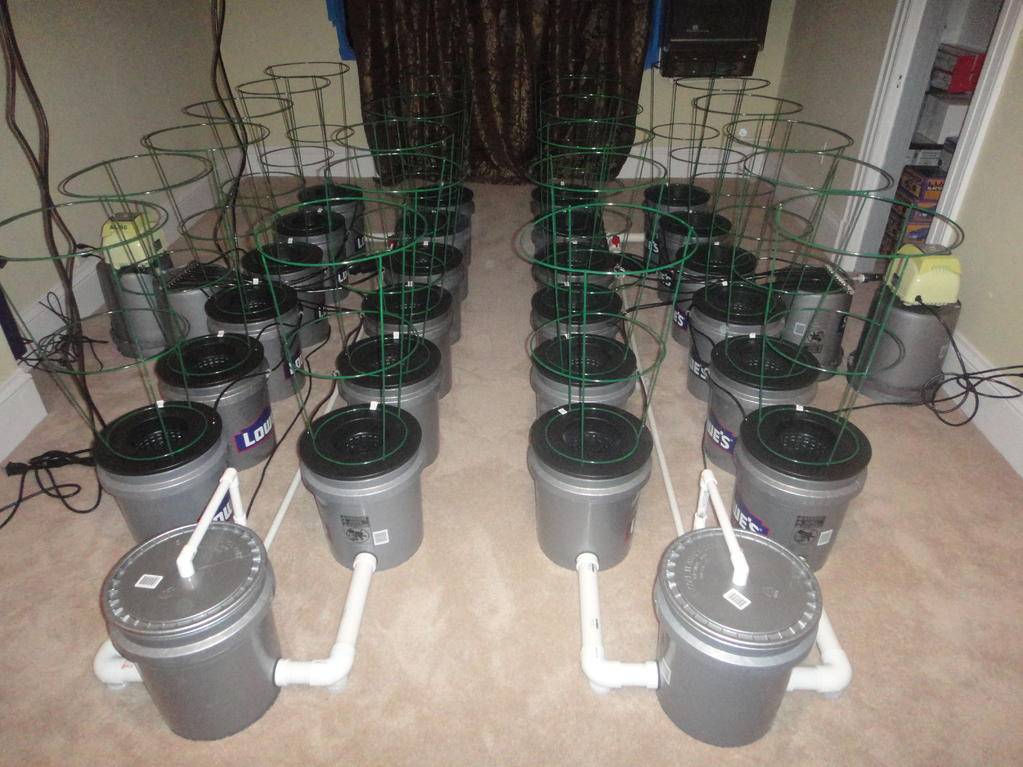
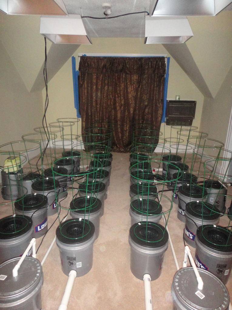
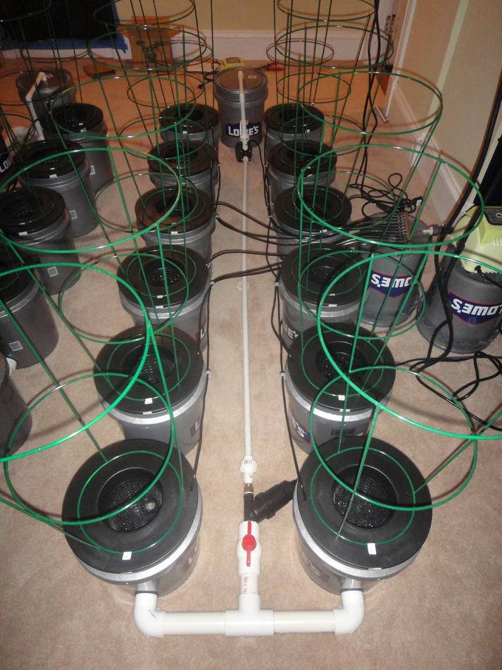
An introduction to working with PVC
After cutting your PVC pipes, you will need to clean all of your PVC fittings with PVC Cleaner. Do not clean any parts that are threaded. For threaded pieces you will need to use Teflon Tape. Any piece of the pipe that has contact with another PVC piece needs to be cleaned with PVC Cleaner. Don’t just clean the pipe and remember to also clean your fittings. I like to use the Clear Cleaner because the purple one will turn your pipes purple and your system won't look as professional. Please go to YOUTUBE and watch a video on how to clean PVC fittings properly.

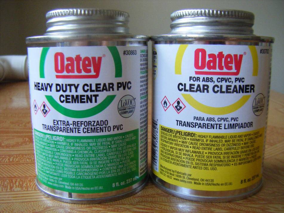
When you are applying the PVC Cement to your fittings, please remember to apply the Cement to both of the pieces that you are connecting. After you apply the Cement to both fittings, give the PVC pipe or fittings a quarter turn as you are inserting a piece into the other piece and make sure that the pieces go in all of the way. Let the pieces dry for 5 seconds and then you can clean any extra Cement off of the pipe/fitting. It is best to use one of the smaller cans of PVC Cement because the pipes are small and the smaller bottles of PVC Cement come with a smaller attached brush. Observe the 8 oz cans of PVC Cleaner and PVC Cement that I use in the picture below:

Warning with the Neoprene Washers
You have to be very careful when you are using the washers. Do not over tighten them to the point where they bend or flex like this picture below:
INSERT PICTURE
These washers are one time use when they are used with the grey fitting because it is actually an electrical fitting and there are raised letters on the piece of the fitting that will make an imprint onto your washers after they are screwed together. To my knowledge I don’t know of any PVC fitting that is straight and allow the fitting to screw all the way in to connect to the bucket. If you happen to know of a fitting to use instead of the grey one, please let us know and I will update this post. When I say the washers are one time use, that doesn't mean that you can't use them for years as long as you don't take the system apart. You don't need to take the system apart to clean it.

Design Change Edit:
The 12 Bucket System has been changed to a 10 Bucket System. For those growers who want to build the new 10 bucket system for 2,000 watts, on top of the new demensions of 8" on the 1.5" PVC pipe, your water pumps will need to be changed to a:

Danner Supreme Classic Model 5

And your air pump can be changed to:

Alita AL-60

This means that the price of the 2,000 Watt system just went down to under $400! Pretty amazing.

The 12 bucket system is better suited for applications which use lights similar to Gavita which gives you a 5'x5' light spread and would make the system 5'x10'. Anyone who is going to go this route, please add an additional 4" to the in-line manifolds and an extra 3" to the 2 sides of the Back Manifold. I will update the thread as soon as I can. Sometime in mid Jan 2014.
 
Last edited:

Snype

Active member
Veteran
Parts List

1.5" Female Adapter PVC Fitting (Carlon) Available at Home Depot and Lowes or www.codale.com for cheaper.


Nibco 1-1/2 in. PVC DWV Hub x SJ Trap Adapter (female). Available at Home Depot. This is for reference from NIBCO: http://www.nibco.com/Fittings/Plastic-Fittings/PVC-DWV-Fittings/4801-7-Trap-Adapter-H-x-SJ-PVC-DWV/


Nibco 1-1/2 in. PVC DWV Trap Adapter (male). Available at Home Depot


Neoprene Washer. 3/16" thickness x 1-7/8" ID x 2-1/4" OD Neoprene, Black in 50 durometer. Available at: reliantrubberco.com.
4 bucket systems = 20 Washers
6 bucket systems = 28 Washers
8 bucket systems = 36 Washers
10 bucket systems = 44 Washers
12 bucket systems = 52 Washers

 
Last edited:

Snype

Active member
Veteran
Parts Continued

1.5" Female 90 Degree PVC Elbow - (Pressure applications) (Mueller) Available at Home Depot and Lowes


1.5” PVC T - (Female) - (Pressure applications) (Mueller) Available at Home Depot and Lowes


1.5" to 1" Bushing - Slip


1" Ball Valve Shut Off - Slip
 
Last edited:

Snype

Active member
Veteran
Parts Continued

1" PVC Union - Slip


1" to 3/4" Bushing. Threaded


3/4" Y Stainless Steel Filter with Flush. Part #F063. Available at DripIrrigation.com
 
Last edited:

Snype

Active member
Veteran
Parts Continued

1.5" PVC Pipe


3/4" - S x FTP - Female Adapter


3/4" x 1/2" Flush Bushing - SPIG X RSoc


1/2" Ball Valve Shut Off - Slip
 
Last edited:

Snype

Active member
Veteran
Parts Continued

1/2" PVC Union - Slip


1/2" PVC Adapter - S x MPT


1/2" PVC Adapter - S x FPT


1/2" 90 Degree - Slip
 
Last edited:

Snype

Active member
Veteran
Parts Continued

1/2" PVC T - S x S x FPT


1/2" Brass Boiler Drain


1/2" PVC Pipe


1" PVC Pipe - Picture not included

Lowes 5 Gallon Bucket Lid - Picture not included

5 Gallon Lowes Bucket
 
Last edited:

Snype

Active member
Veteran
Drilling holes in the buckets and bucket lid

On Lowes buckets, you will notice 2 market lines that are parallel to each other. This is a great feature on the Lowes buckets and one of the reason's of why I use them because I can drill my holes using the 2 parallel lines as a guide. (I'm advising everyone not to use any other company round bucket. Other buckets are not made exactly the same at the bottom and can have very minor leaks.) On Lowes Buckets, look at the lines on the bottom of the bucket where we will find our parallel guide:


I make my template from a piece of cardboard from the top of a box of Cheerios. After folding the piece of cardboard in half, I mark a 2" line with a marker as seen below:


Now I line up the cardboard onto the bucket right on the line that is on the Lowes bucket as seen below:


After I mark my bucket, I use a 1-7/8" (48mm) drill bit and drill my hole. A trick that you can use after you drill the pilot hole, you can drill the bit in the reverse direction to achieve a cleaner cut. Don't press the bit onto the bucket when the drill is off. You will want the bit to be spinning before making contact with the bucket. This is what it looks like when the hole is drilled:


After you drill your holes in the buckets, make sure to smooth any rough edges so that the Neoprene Washer makes perfect contact with the buckets. If you don't do this properly you could have a small leak. I use my finger nail to do this process.
 
Last edited:

Snype

Active member
Veteran
Building the manifold for systems using 250 watt or 400 watt lights

Part List for 2 Row Manifold, 250 Watt or 400 Watt Lighting
(2) 1.5" Male PVC Trap Adapter (Nibco)
(2) 1.5" Female PVC 90 Degree Elbow - (Pressure applications)
(1) 1.5” PVC T - (slip) - Pressure applications
(1) 1.5" to 1" Bushing - Slip
(2) 1.5” PVC cut to a lenth of 6-7/8"
(2) 1” PVC cut to a length of 5"
(1) 1” Ball Valve Shut Off (slip)
(1) 1" Union - Slip
(1) 1" to 3/4" Bushing - Threaded
(1) 3/4" Stainless Steel "Y" Filter with Flush
PVC Cleaner (Clear Cleaner)
PVC Cement (Heavy Duty)
Teflon Tape

When cleaning and cementing your PVC Unions and Ball Valves, make sure the valve is in the open position and that you take apart your Union beforehand so that you don't ruin your Union Washer and Ball Valve.

Step 1:
With the PVC Cleaner, clean the inside of the two PVC 90 Degree fittings, your two 6-7/8” pieces of PVC pipe, and your PVC Trap Adaptors. If you don’t know how to do this please look it up on YouTube. Apply the PVC Cement to the trap adaptors and the 90 Degree fittings and connect them together. If you don’t know how to do this please look it up on YouTube. After those pieces dry, apply the PVC Cement to the 90 Degree fittings and one end of the 6-7/8” PVC pieces and connect them together. It should look like this when it’s done:


Step 2:
Apply the PVC Cement to the other end of the 6-7/8” PVC Fittings and 2 out of the 3 holes of the PVC T Fitting and connect them together one at a time. You can put it on your floor as your doing it to make sure that it is nice and straight when you are doing it. It should look like this when it’s done:
Insert Picture

Step 3:
With the PVC Cleaner, clean the inside of the Shut Off, the outside of the 2 piece's of 5" PVC pipe and the bushing. Apply the PVC Cement to the Bushing, the Shut Off and the (2) 5" piece of PVC pipe. Attach the Bushing to the Shut Off and then attach one end of the PVC pipe to the other end of the Shut Off. Once that dries, apply the PVC Cement to the other side of the PVC pipe and the last hole in the PVC T fitting and attach them together.

Step 4:
With the PVC Cleaner, clean the inside of the 1" Union and the 1" x 3/4" Bushing and Cement them together. Put 3 rotations of Teflon Tape onto the Y-Filter in a clockwise direction and screw it into your manifold that you just built. Your 4 bucket manifold is now built and should look like this:
 
Last edited:

Snype

Active member
Veteran
Building the manifold for systems using 600 Watt or 1000 Watt Lighting
The manifold that you build will depend on if you have 2 rows or 3 rows of plants. When you choose to go with 3 rows, you will want to grow smaller plants that may not bush out as much as other plants can. I find that plants that finish flowering at around 36" in the 3 row system is perfect for good light penetration and high yields. Plants that grow more of a main donkey dick colas are most suitable for this application but you can grow any plant that you choose. With the 2 row systems I have grown plants up to 60” although you don’t get the intense light penetration in the lower end of your plants. If you choose to go with the 2 row system, it is best to have a nice topped plant to grow, that bushes out if you want to achieve a gram per watt easier. You will want to do your own testing to see which system will suit the needs of your specific plants. Each system has 16” plant centers in line but across the rows, the 3 row system stays with 16” plant centers and the 2 row system goes to 21.25” plant centers across. Here are the parts that you will need for the 2 row manifold:

Part List for 2 Row Manifold, 600 Watt or 1000 Watt Lighting
(2) 1.5" Male PVC Trap Adapter (Nibco)
(2) 1.5" Female PVC 90 Degree Elbow - (Pressure applications)
(1) 1.5” PVC T - (slip) - Pressure applications
(1) 1.5" to 1" Bushing - Slip
(2) 1.5” PVC cut to a lenth of 8-1/2"
(1) 1” PVC cut to a length of 7"
(1) 1” PVC cut to a length of 2"
(1) 1” Ball Valve Shut Off (slip)
(1) 1" Union - Slip
(1) 1" to 3/4" Bushing - Threaded
(1) 3/4" Stainless Steel "Y" Filter with Flush
PVC Cleaner (Clear Cleaner)
PVC Cement (Heavy Duty)
Teflon Tape


When cleaning and cementing your PVC Unions and Ball Valves, make sure the valve is in the open position and that you take apart your Union beforehand so that you don't ruin your Union Washer and Ball Valve.

Step 1:
With the PVC Cleaner, clean the inside of the two PVC 90 Degree fittings, your two 8.5” pieces of PVC pipe, and your PVC Trap Adaptors. If you don’t know how to do this please look it up on YouTube. Apply the PVC Cement to the trap adaptors and the 90 Degree fittings and connect them together. If you don’t know how to do this please look it up on YouTube. After those pieces dry, apply the PVC Cement to the 90 Degree fittings and one end of the 8.5” PVC pieces and connect them together. It should look like this when it’s done:


Step 2:
Apply the PVC Cement to the other end of the 8.5” PVC Fittings and 2 out of the 3 holes of the PVC T Fitting and connect them together one at a time. You can put it on your floor as your doing it to make sure that it is nice and straight when you are doing it. It should look like this when it’s done:
Insert Picture

Step 3:
With the PVC Cleaner, clean the inside of the Shut Off, the 7" piece of 1" PVC pipe and the bushing. Apply the PVC Cement to the Bushing, the Shut Off and the 2" piece of PVC pipe. Attach the Bushing to the Shut Off and then attach one end of the PVC pipe to the other end of the Shut Off. Once that dries, apply the PVC Cement to the other side of the PVC pipe and the last hole in the PVC T fitting and attach them together.

Step 4:
With the PVC Cleaner, clean the inside of the 1" Union and the 1" x 3/4" Bushing and Cement them together. Put 3 rotations of Teflon Tape onto the Y-Filter in a clockwise direction and screw it into your manifold that you just built. Your manifold is now built and should look like this:
 
Last edited:

Snype

Active member
Veteran
Building the In-Line Bucket Manifolds
These are the manifolds that will link together buckets in the same row.

Part List for In-Line Bucket Manifold
(2) 1.5" Female PVC Trap Adapter (Nibco)
(1) 1.5" PVC pipe cut to a length of 4.5”
PVC Cleaner (Clear Cleaner)
PVC Cement (Heavy Duty)

Step 1:
With the PVC Cleaner, clean the inside of the Trap Adaptors and the 4.5” piece of pipe. Apply the PVC Cement to all of the pieces and attach them together. Repeat this process for as many manifolds that you need. For example for a 12 bucket system you would need 10 In-Line Manifolds. Your manifold is now built and should look like this:


Building the L manifolds for the 4 Plant System
The L manifolds connect the rows of buckets to the controler or epicenter.

L Manifolds Part List for the 4 Plant System
(4) 1.5" Female PVC Trap Adapter (Nibco)
(2) 1.5" 90 Degree PVC Elbow - (Pressure applications)
(2) 1.5” PVC cut to a lenth of 15"
(2) 1.5” PVC cut to a lenth of 2-7/8"
PVC Cleaner (Clear Cleaner)
PVC Cement (Heavy Duty)

Step 1:
With the PVC Cleaner, clean the inside of the Fittings and the 4 pieces of PVC Pipe. Apply the PVC Cement to 1 side of your 90 Degree Elbow and the 2-7/8" piece of PVC Pipe and connect them together. Let it dry for a few minutes after you connect it. When the piece has dried, cement your Female Trap Adapter to the other side of the same PVC Pipe that you just used.

Step 2:
Apply the PVC Cement to the other side of your 90 Degree Elbow that you just used and the 15" piece of PVC Pipe and connect them together. Repeat this process for the other L-Manifold. Your manifolds are now built and should look like this:
Insert Picture


Building the L manifolds for the 6 and 12 Plant Systems for 600 Watt or 1,000 Watt Lighting
The L manifolds connect the rows of buckets to the controler or epicenter.

L Manifold Part List for the 6 and 12 Plant Systems
(4) 1.5" Female PVC Trap Adapter (Nibco)
(2) 1.5" 90 Degree PVC Elbow - (Pressure applications)
(2) 1.5” PVC cut to a lenth of 10"
(2) 1.5” PVC cut to a lenth of 3.5"
PVC Cleaner (Clear Cleaner)
PVC Cement (Heavy Duty)

Step 1:
With the PVC Cleaner, clean the inside of the Fittings and the 4 pieces of PVC Pipe. Apply the PVC Cement to 1 side of your 90 Degree Elbow and the 3.5" piece of PVC Pipe and connect them together. Let it dry for a few minutes after you connect it. When the piece has dried, cement your Female Trap Adapter to the other side of the same PVC Pipe that you just used.

Step 2:
Apply the PVC Cement to the other side of your 90 Degree Elbow that you just used and the 10" piece of PVC Pipe and connect them together. Repeat this process for the other L-Manifold. Your manifolds are now built and should look like this:
Insert Picture
 
Last edited:

Snype

Active member
Veteran
Assembling The First Row In Your RDWC Systems
No matter what system that you choose to build, they are all set up in the same manner.

Step 1: Place a neoprene washer onto each end of your back manifold. Insert the manifold into 2 buckets. You can use the buckets so that the Lowes Logo points toward each other so that if you walk around the system, you don't see the Lowes Logo. This will look better for visual purposes. With the manifold inserted into 2 of your buckets, place another neoprene washer into the bucket onto the manifold. Very lightly screw in your 1.5" Female Adapters. You do not need to make it tight at this point until the entire system is built. After the entire system is built is when you go back and tighten your fittings.
INSERT PICTURES

Step 2: Install the first row of buckets of your specific system and use the In-Line Manifolds in the same manner as Step 1. Remember that you need 4 washers for each bucket. You have now assembled your first complete row of buckets and are ready to build the next manifold from the Y-Filter to the In-Line Pump and Controller/Epicenter.
INSERT PICTURE
 
Last edited:

Snype

Active member
Veteran
Building and installing the feed line to and from the pump to the controller/epicenter


Part List for the feed line to and from the pump to the controller/epicenter
(1) 3/4" - S x FTP - Female Adapter
(1) 3/4" x 1/2" Flush Bushing - SPIG X RSoc
(2) 1/2" Ball Valve Shut Off - Slip
(2) 1/2" PVC Union - Slip
(1) 1/2" PVC Adapter - S x MPT
(1) 1/2" PVC Adapter - S x FPT
(2) 1/2" 90 Degree - Slip
(1) 1/2" PVC T - S x S x FPT
(1) 1/2" Brass Boiler Drain
1/2" PVC Pipe (57.75" for 12 site RDWC system)
PVC Cleaner (Clear Cleaner)
PVC Cement (Heavy Duty)
Teflon Tape
When cleaning and cementing your PVC Unions and Ball Valves, make sure the valve is in the open position and that you take apart your Union beforehand so that you don't ruin your Union Washer and Ball Valve.

Step 1: After cleaning all of your pieces with your PVC Clear Cleaner, Cement the (3/4" - S x FTP - Female Adapter) and (3/4" x 1/2" Flush Bushing - SPIG X RSoc), After you Cement them together, let them dry for a few minutes.

Step 2: Cement your (1/2" Ball Valve Shut Off - Slip) to the piece that you made in step one using a pice of 1/2" cleaned PVC pipe.

Step 3: Cement your (1/2" PVC Union - Slip) to the (1/2" PVC Adapter - S x MPT) using a small piece of cleaned 1/2" PVC Pipe and let it dry for a few minutes.

Step 4: Cement the piece that you made it Step 3 to the piece that you made in Step 2 with 1/2" PVC Pipe.

Step 5: Put 3-4 clockwise rotations of Teflon tape onto the Y-Filter and your piece that you just finished in Step 4. Screw your new finished manifold into the Y-Filter. Unscrew your 1/2" Union from the manifold that you just built and screw the threaded piece into your pump and then screw back the Union.

Note on your Pump:
This pump is for the 4 plant system:
http://www.marinedepot.com/Danner_M...ps-Danner_Mfg.-DN1119-FIWPSBUF-DN1121-vi.html

This pump is for the 6 plant system:
http://www.marinedepot.com/Danner_M...ps-Danner_Mfg.-DN1119-FIWPSBFT-DN1123-vi.html

This pump is for the 10 plant system:
http://www.marinedepot.com/Danner_M...ps-Danner_Mfg.-DN1119-FIWPSBFT-DN1123-vi.html

This pump is for the 12 plant system:
http://www.marinedepot.com/Danner_M...ps-Danner_Mfg.-DN1119-FIWPSBFT-DN1125-vi.html

Step 6: Put 3-4 clockwise rotations of Teflon tape onto the (1/2" Brass Boiler Drain) and your Inline Water Pump that goes with your System Model explained above.

Step 7:

I will finished the rest of this post later today.
 
Last edited:

Snype

Active member
Veteran
Installing The Final Row In Your Systems And Completing Installation

Step 1: Screw in your final row of buckets. Remember that you need 4 washers for each bucket. You only need to loosely tighten the Female adaptors because you will screw them all the way in after your build your system.

Step 2: Now attach your L-Manifolds from the rows of buckets to the controller/epicenter. You will do this in the same manner that you used for all the other buckets.

Finish the rest later.
 
Last edited:

Snype

Active member
Veteran
How I Run My Systems Successfully

Choosing the correct Air Pump to use
From the testing that I have done I have figured out the minimum required air that you will want to use. In these calculations I’ve taken into account that depending on your environment, your water temperatures will vary. The warmer the water is, the less Dissolved Oxygen that it can hold. I make my calculation in Liters so we will think about it this way here. Each 5 Gallon bucket in the system that you choose to build, will hold a maximum of 4 Gallons of water and in terms of Liters, that would be 15 Liters. Now you want to multiply the amount of buckets that you are going to use by 15 Liters. For example if you are using the 12 plant system, then you multiply 15 Liters x 12 buckets, which would give you 180 Liters. For whatever application that you choose to use, you want to use an air pump rated at half of those liters per minute. So in a 12 plant system you want a pump rated around 90 Liters per minute. You do not have to enter the control bucket into your calculations because the waterfall that is created by the water pump going into the controller supplies all the Dissolved Oxygen that you need. If you are using more than 6 buckets, I would suggest that you spend the extra money and get the Alita brand air pumps. They really are top of the line and it is a minimum expense for what you are going to get out of your yield and product. If you want to go the cheaper route, then any air pumps rated at the calculations above will work.

Choosing the correct Water Pump to use
Personally I like the water in my system to re-circulate at least every 5 minutes. This keeps your nutrient and pH in the system consistent. Most in-line pumps in my area are rated in Gallons Per Hour so we will use Gallons in our calculations here. Each bucket in the system holds a maximum of 4 Gallons of water. So we will take that number and multiply by the number of buckets that you have. For example in a 12 plant system, we have 13 buckets of water so we multiply that by 4 Gallons per bucket and get 52 Gallons. We want the water to re-circulate at least every 5 minutes and there are 12 five-minute periods in an hour, so we multiply 52 Gallons by 12 Cycles to get 624. This means that you want an in-line water pump that is rated for at least 624 Gallons Per Hour.

Chlorine as a preventative measure
Anyone who doesn’t use live nutrients or supplements in hydroponics, I would advise to keep a residual level of 0.50 PPM Chlorine at all times as a preventative measure against plant pathogens and future root problems. Always remember that too much Chlorine will kill your plants and you never want to put more than 1.0 PPM of Chlorine for large healthy plants. Cuttings and smaller plants are more sensitive to Chlorine and you will want to keep only 0.50 PPM of Chlorine so that you don’t risk killing them. My dropper gives 22 drops / 1 mL of liquid. Before giving Chlorine to small reservoirs you will want to see how many drops per mL your dropper gives so you give a safe amount of Chlorine. My dropper gives a 0.50 PPM of Chlorine at the rate of 1 drop of Clorox Bleach / 2 Gal. To give 0.50 PPM of Chlorine using Clorox Bleach, the equation is 1 mL of Clorox Bleach / 44 Gallons. Always take into account if your tap already has Chlorine in it and adjust your equation. Remember in a well aerated solution, Chlorine naturally disappears in 3-4 days so add in your Chlorine every 4 days as a preventative measure against future root and pathogen problems. Add this to your normal schedule and you will see how hard it is to get root problems again.

How high to hang your reflector
All hoods are different and you would have to find the sweet spot with a light meter. The way that I find my sweet spot is to pay attention to the 4 corners that the light is going to cover. Pretend that there is a grid there. Start at around 36" for the height of your reflector and put your meter on the tray where the 4 corners would be on the imaginary grid. You can actually make a grid with a 4x4 flattened cardboard box. This is what I do. You will have to adjust where the light goes when all 4 corners read the same number on your light meter. Now your light is centered.

Now you have to see how high your reflector should be from the tops of the plants. Keep lowering your reflector on toward your 4 foot grid. Put your light meter on the on the corners of your 4 foot grid and keep lowering your reflector and you will see the numbers on your light meter rise. When the numbers on the 4 corners of the 4 foot grid start going down, then you have gone too far. Now take a measurement of how high the reflector is from the grid. This is how high your reflector should be from the very top of your plants when they are fully grown.

pH
pH is very important when you are growing cannabis. Growing cannabis in soil and growing plants hydroponically require totally different pH’s so don’t be confused by this. I will only talk about pH in RDWC with hydroton as a medium here. You want to stay in a range of 5.8 – 6.2 at all times. Falling below or above this mark can cause serious problems. If your solution is not pH’d to the correct numbers, then the plants will not be able to receive and use the nutrients that you are supplying to them.

I have a lot of experience with many company's pH and TDS / PPM meters. When you buy one of these devices from a grow shop it usually means that you did not buy an expensive lab grade model and the result is that your device is made with cheaper components. I understand that most growers don't have thousands of dollars to buy a lab grade meter and this is ok but there are some things that you must know. With my testing with Hanna, Nutradip and Blue Lab I see similar problems in them that can give you a false reading.

Just because you might have a top of the line pH meter (pH meter is a necessity in hydroponics) doesn’t mean that the reading that it is giving you is correct. There are a few factors that will give you a false reading. Here is a list:

1. Your calibration solution is contaminated, old or was stored in high temperatures or exposed to light for too long.

2. There is a build up of gunk on the pH probe. Solution: Gently clean the probe with a soft brush and recalibrate.

3. pH probe is broken or it’s beyond its life span. Buying pH meters at grow shops is an economical way of acquiring a meter but it is not lab grade and cheaper components are used in the process. pH probes can damage very easily and are also sensitive. When the pH probe is not being used, it is very important to keep it in 7.0 calibration solution. When you open the box for the first time from buying the meter, there is not always solution attached to the bottom of the probe but it is dipped in some sort of salt so don’t be confused by this and think that you can store your probe without solution. Your probe will eventually dry up and break if you were to dry it out. It is very simple to know if you have a damaged probe. This process will require 2 different calibration solutions (pH 4, pH 7 or pH 10). Most meters that I’ve seen in the US use pH 4 and pH 7. Your owner’s manual will tell you if you have to use the 7 or the 4 first. It is important to listen to what the company of the specific meter that you have tells you. If your meter does not contain a computerized calibration method then you will see that you calibrate it with a screw driver or there are knobs that you turn or you may have to digitally punch in numbers to a screen on your device. If your meter calibrates to a screw driver or some sort of knob that you turn then it is important for you to know that when you pH the 4 first and finish, you then clean the probe and insert it into the pH 7 calibration solution. If you insert the probe into the 7 and it doesn’t read pH 6.8, 6.9, 7.0 or 7.1, 7.2 (normally I wouldn’t insert the 6.8 or 7.2 in here but the meters at grow shops are not lab grade and have a greater margin of error), then your probe has gunk on it or is broken and needs to be replaced. You can try to recalibrate it but it will not work because it will move the pH 4 somewhere else and you’ll keep going back and forth just wasting time. You will usually have to do some tweaking going back and forth between the pH 4 and 7 solution because there is a lot of little spaces between 4.0 - 4.1 and 3.9 - 4.0 as well as 6.9 – 7.0 and 7.0 – 7.1. Once you get the meter to read 4.0 and 7.0, then your meter will be accurate for at least that usage but you should calibrate your meter once a week to be safe. Your meter is a computer and you can’t just trust the numbers that it is spiting out at you. Always question the reading that you are getting and compare it to what your plants are telling you. The first signs that you will usually see first, if your probe goes out of alignment, is yellowing of the edges of fan leaves (Magnesium Lockout) or brown / black spots on leaves (Calcium Lockout). If you have the solution up to the required PPM and you see these signs on the leaves, then that should be a big read flag and will require you to calibrate your probe or check if it is broken and get a working one. You will notice within a period of time, the pH of your solution will fluctuate. Depending on what different things that you add to your Rez can make the fluctuation different so if your solution normally rises and then you add something else to the mix and then it does the opposite then it’s good to keep this in mind. If you know that your solution rises, then set your solution to 5.8 and let it climb to 6.2 and then pH it down, if your solution falls, then set it to 6.2 and let it fall down to 5.8 and pH it back up. This fluctuation should not peak within a 24 hour period with most nutrients so if you see this happen you most likely have root problems (root rot / pythium) or some sort of pathogen, fungus or algae. We will cover this in another chapter.

4. RF interference from your digital/electronic ballast. RF interference has a major affect on many pH / TDS / PPM meters that are sold at grow shops. It is important that your ballasts and any equipment that gives off RF is turned off before calibrating and using your meter. I have spent countless hours on the phone with the owners of these company's complaining about how the RF interference from my ballasts are affecting my reading and they would send me brand new meters that would have the exact same problem. Make sure all your equipment is turned off when using your meters.

Feeding
Variety of strains requires different amounts of nutrient levels. This is why you wouldn’t want to grow multiple types of strains in the same system at the same time. If you have some heavy feeding strains mixed with underfeeding strains, it would be impossible to meet the needs of both types at once. For this purpose, it is always best to have all your plants in each system from the same mom in clone form. Of course you can grow similar feeding strains together but you would not maximize the yield of the grow and this is about maximizing your grow.

Overfeeding can cause lack of flavor in your final product and usually does. I will explain how to learn what your plants want by using your EC/TDS/PPM meter. Having one of these meters is a necessity when growing hydroponically and if you don’t have one you are flying blind. Always make sure that your meter is calibrated and that you check re-calibrate the meter every 2 weeks and when you see potential problems going on. Most grow shop meters are made with cheap components and are not lab grade so reading can be off frequently throughout your grow.

I believe in growing in sterile growing systems at all times. This doesn’t mean that growers who do use live nutrients or suppliments are wrong but this isn’t what this manual is about. Things can go wrong real fast in hydroponics and potentially kill your whole crop within days. Because of this I use refined nutrients and the brand that I like to use is General Hydroponic Flora Series. I enjoy the results that I get with this product but I mainly use it because I can keep my pH more stable with it compared to some other brands. Whatever brand you choose you will notice how the pH acts and if it swings too much you can try another brand and see what works for you. When I use GH Flora, I only use the Micro and the Bloom. The Micro has all the nitrogen that you need in your grow. 1 part micro to 1.5 parts bloom for VEG stage and 1 part Micro to 2 part Bloom for Flowering stage. You will first have to test all your clones in the same system to see how these plants eat so you can maximize the yield without burning them and ruining your flavor. The way that I do this with my nutrients is once I have roots, I start with a low PPM around 300. I keep data and write down what the PPM is every day once I top off the rez to the same point that it was when I first put the nutes in when it was 300. What I want to see is the PPM come down but not real fast. If your meter is reading 240 in 3 days then I would raise the solution to 360 and continue to record this data. I know that I am where I want to be when the meter is only going down 010 ppm per day. I like to look over a 3 day period cause it is hard to see 10-20 PPm per day as opposed to 60 ppm over a 3 day period. If the PPM is not going down then you are too high so when you raise it you don’t want to go too high or you’ll have to change out your system and nute at a lower level. As your plants are growing, you are recording the data that you get and when it reaches the levels of 10-20ppm of a decrees per day, then you know how much to use on your future grows with that pheno.

Throughout the years I’ve learned to keep it as simple as possible and don’t be fooled by variety of high priced snake oils that the grow shop has to offer. Cannabis doesn’t require as much as most growers think and a lot of new growers and even people who have years of growing experience make the mistake of following the directions on nutrient bottles. This can fry your plants.
 
Last edited:

Snype

Active member
Veteran
I've been to many stores to find the 2 types of net pots that can work together for me. You will have to do the same unless you shop at Worms Way. They have the perfect 2 pots that can fit together. For the RDWC system I use a 6" Bucket Lid Net Pot. They are not the same from all stores so you must test it yourself to find ones that can work together. I cut the bottom off of the HydroFarm 6" Bucket Lid Net Pot (Model #HG6RDBK). I cut off the bottom with a razor blade. Here 2 pictures of before and after:


The other pot that goes into the VEG-A system is a 5" Daisy Flex Net Pot. I purposely bought hundreds of them incase they go away one day. Here is what it looks like:


When the roots grow in the VEG-A system, I transfer them into the RDWC System by first dunking the roots into my nutrient solution for a few seconds then then gently placing them into the 6" Bucket Lid Net Pots wile making a turning motion. The end result is that now the roots are hanging right into the solution from the first day of them being placed into the RDWC System.
 
Last edited:

Snype

Active member
Veteran
7600 Watt Systems With Horizontal And Vertical Lights
The 7600 Watt Package is (2) 12 bucket systems. Everything about the 2 systems is exactly the same as the 2,000 watt system in every way. The only difference is that after you hang your 4 horizontal 1,000 Watt reflectors, you add (6) 600 Watt Vertical Bulbs. You will have (2) 600 Watt Vertical Bulbs for each row. So between each system you will hang (2) 600 Watt Vertical Bare Bulbs and then you will also have (2) 600's on the other side of each system which will give you 7,600 Watts! I like to use reflectors pointed sideways (mounted to the wall) for the 2 outer rows and bare bulbs between the 2 systems. Pictures coming later...
 
Last edited:

Snype

Active member
Veteran
Upgrades
One of the upgrades for these systems is a pressure gauge. The pressure gauge is so that you can know if you need to clean out your Y-Filter or if you have a clog in the system. This makes it easy to not have to check the Y-Filter from time to time. This is a close up of the pressure gauge attached to the system:
INSERT PICTURE
 
Last edited:
Top