Now that I am finally done with my lengthy project of building a hybrid PL-L/LED luminaire, I thought that I would write it up so that others might get some benefit from my experience. As this is being written, the luminaire has gone through a 2-week burn-in and has now been moved into my scrog tent.
First of all, I would like to thank a couple of the people who were crucial to its development. Knna is the first one that comes to mind – his tutorials on building LED fixtures on numerous web sites was critical to my understanding of what was necessary, and although I ultimately didn’t use his assembly technique, he was the origin of my understanding the mechanics of what was required. In addition, he worked with me through numerous PM exchanges, assisting me in the evolution of thought that took me from a ”conventional” LED application with two or three spectrums to what you see here.
Shafto was another contributor to the knowledge base that brought this about – his posts on MCPCB’s and plate re-flow soldering directly contributed to the successful completion of this project. Additionally, virtually everyone that has posted about DIY LED fixtures in the last couple of years has made some contribution to this. Unfortunately, I can’t claim that the hybrid concept is wholly original – once I had the design concept in mind, I found that Old Mac had built something on the same principle several years ago, Ahhhavalanche has his Magma Chamber, and there are undoubtedly many others.
The concept was developing about the same time that some of the commercial manufacturers were starting to bring out luminaires with more than the once-standard red/blue mix. I had used a home-made 6 x 55 watt PL-L fixture, and was impressed with the results. Further research showed that the PL-L lamps in virtually all available color temperatures had a very good spectral distribution with the exception of being weak in the far-red area.
I generally grow in a SCROG format, so the somewhat limited penetration of these lamps wasn’t really an issue, and they lent themselves well to covering the entire grow area rather than a point source or the rather limited form-factor of most existing commercial LED products. I decided to combine the two technologies because it worked quite well for the form factor that I wanted to achieve and it seemed like a much more economical and effective approach to getting full spectrum lighting. Using exclusively LED’s to achieve a full spectrum is counter-intuitive to me – combining very narrow outputs to achieve a broad spectrum doesn’t make sense, and it is quite expensive if you use good components.
I decided to purchase a commercially-made fixture in order to get some experience with any peculiarities that are brought to growing with the usage of LED's, and also to take the pressure off of getting things done more quickly than I was comfortable with. After lots of research, I settled on the Lumigrow ES330, which ultimately set a pretty damn high standard for what I would build. As a retired industrial electrician, I could appreciate the construction techniques and build quality that go into that product line, and as a grower I came to appreciate how well it functioned. Ultimately, I can attest to the fact that even as expensive as the Lumigrow products are, they are a bargain! I have to thank SOTF420 for his input on that purchase.
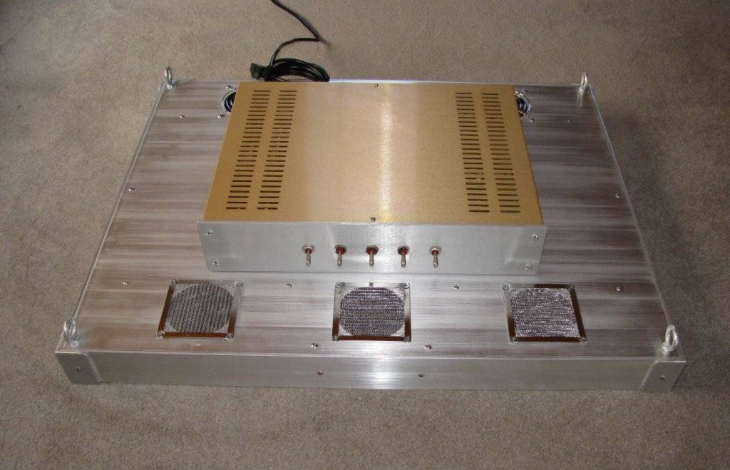
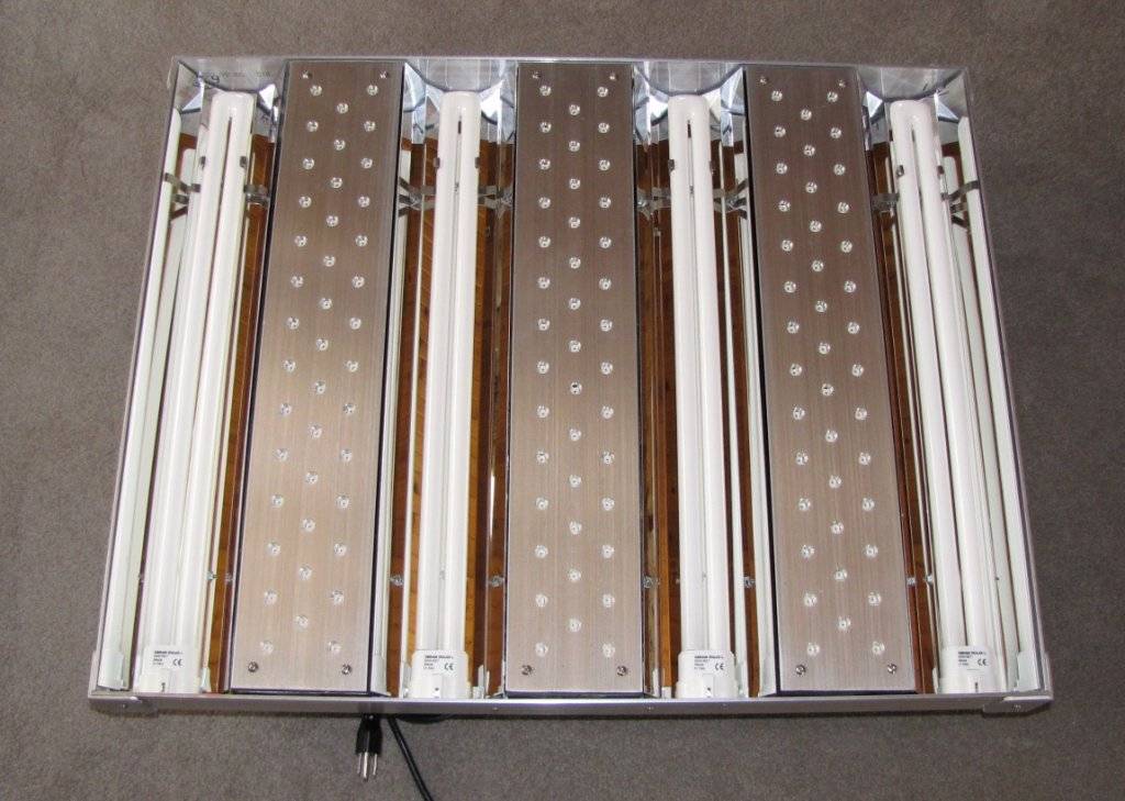
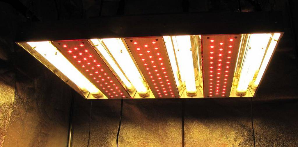
The ES330 showed me that while it was a very effective light source, it lacked a bit in giving me an even, edge-to-edge coverage of my screen. My former PL-L fixture was far superior in that respect, so the design started to take shape in that direction. I decided to build something with a similar form-factor, but with the addition of 660nm LED’s. The final design was established as utilizing (4) 55-watt PL-L lamps interspersed with (3) LED bars of similar dimensions (4” x 22”). This gave an overall footprint of 22-1/2” x 28-1/2”, which worked well with a 30”x 30” screen.
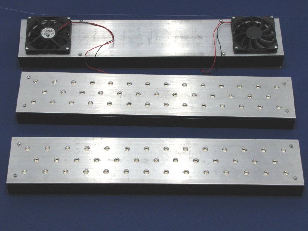
Each LED bar is built around a heat-sink that is 4”x 22” x 1.3”, with (11) 1” tall fins, and black anodized. There are (41) Osram Golden Dragon Plus LED’s mounted on MCPCB’s glued to each one. Although I wanted a passive design to avoid fan noise, calculations showed that the heat-sinks would only support 35-40 watts without additional airflow. I didn’t want to be restricted by this if it turned out that more far-red was needed for the best spectral distribution, and there were too many limitations put on the fixture design by trying to keep the fins open for passive heat shedding. I was also concerned about the additional thermal load of the PL-L reflector assemblies mounted immediately adjacent to the sides of each bar. Reluctantly, the final design uses 7 (!) fans. There are (2) Delta 12-volt 92 x 15 mm fans turning 1800 rpm at 12vdc on each heat-sink. They are rated at 26 cfm and 25 dB’s at full voltage. These fans were set up with one pushing and one pulling, and mounted on an aluminum plate cut to match the footprint of the heat-sink. There is also a single small fan pushing air into the ballast/driver enclosure. End plates were epoxied onto the heat-sinks to keep the air properly directed. The fans also serve as standoffs for the LED bar when it is inserted into the housing, with the space between the fans providing a raceway for the wiring.
Each LED bar (with its cooling fans) is individually switched, as are the PL-L ballasts. This will allow the fixture to be lit up from the center out if that is desirable when the plants are small. With the fan-forced airflow, each bar is capable of easily pushing at least 60 watts, so the luminaire is capable of a minimum of 400 watts ((4 x 55) + (3 x 60)). The Golden Dragons have a very wide viewing angle of 170 degrees, so hopefully they will be well balanced with the distribution and penetration of the PL-L’s. This viewing angle was tightened up a bit by the cover-plate design, which blocks enough of the horizontal light distribution to keep it out of your eyes when working below the fixture but still gives good coverage across the screen.
The LED’s were mounted on the MCPCB’s using the hot plate method detailed for me by Shafto. My particular spin on this was to use an inductive hot plate with the stainless steel “interface disc” that is sold for use with standard cookware. The interface disc is ¼” thick, 8” in diameter, and has a nice handle on it. The combination worked very well – this type of hot plate heats up and cools down quickly, and while the disc would have been large enough to have done numerous components at the same time, I stuck with soldering them 6 at a time. I didn’t want them soaking up too much heat from sitting on the disc for too long before I could pick them off after they had been soldered, or spread over the disc so widely that there would be variations in the time it took to heat them up. This technique worked exceptionally well, with zero failures from the soldering process. The LED’s were positioned on the MCPCB’s freehand, using the labeling on the face of MCPCB as a rough guide for placement.
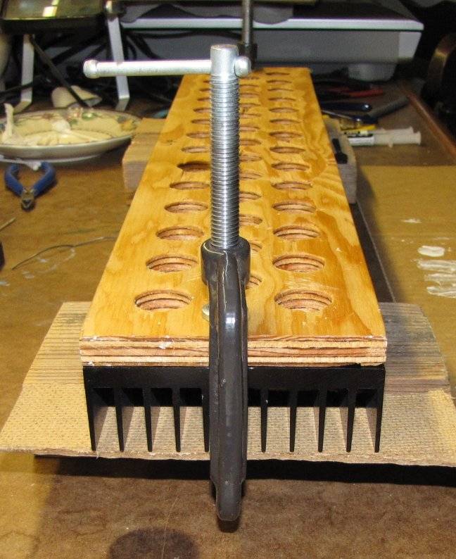
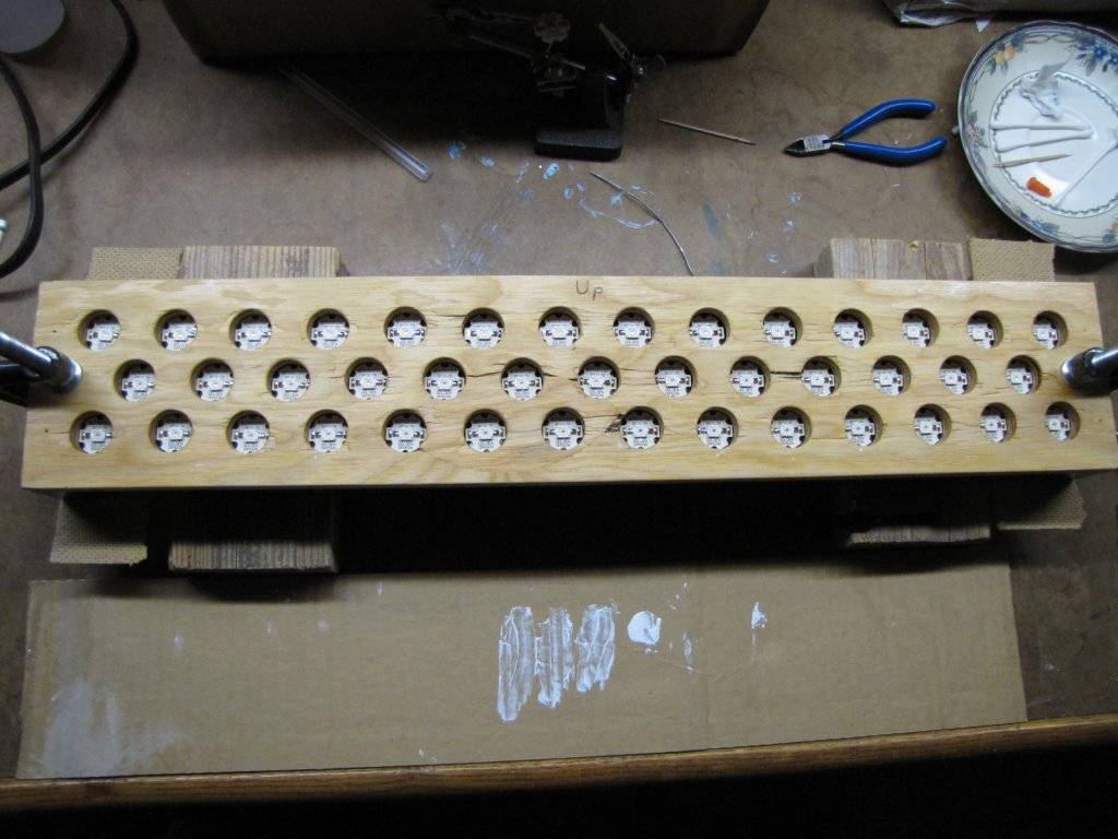
The assembled LED’s were positioned onto the heat-sink with the aid of a wooden template that was clamped to the heat-sink Holes were drilled in the template to place the loaded MCPCB’s in, with enough clearance to jockey them around a bit. This clearance, combined with the freehand placement of the LED’s, created some minor problems with getting the holes in the cover plates where they needed to be. If I were going to do this build again, I would find ways to tighten up the variation in the final placement of the components to mitigate this problem.
After the epoxy had set, the clamps were taken off and the template removed. The MCPCB’s were then wired to form 2 series strings. Soldering of the leads onto the stars was no fun – the heat-sink is both large and efficient, and trying to get things up to soldering temperature was difficult. I was glad that I had thought to tin the solder pads with liquid solder when the plate soldering process was going on, because that helped a great deal. By the time the 3rd bar was completed, my technique had improved considerably!
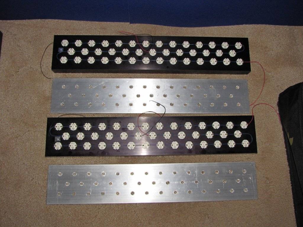
I had struggled with the best way to protect the components and the wiring. I didn’t want to use a clear plastic that would block some of the light, and eventually decided on an 1/8” aluminum plate with holes drilled on the same centers as the LED’s. The plate was spaced off of the surface of the heat-sink so that the LED lenses just entered the holes in the plate, and then each hole was chamfered. The chamfering provided a somewhat polished surface, hopefully acting as a crude reflector to narrow down the Golden Dragon’s 170-degree viewing angle. After all of the machine work was done on the cover plates, the surface was brush-finished with sandpaper, the counter sunk holes buffed, and a couple of coats of clear lacquer was applied. The plates were attached to the heat-sinks with #8 button-head screws and 3/16” nylon standoffs.
Somewhere in the process of fitting the cover plate, the back plate, and all of the associated drilling and tapping, I made a costly mistake. The long power leads from each end of the power circuitry had been left attached to the LED’s after the wiring and testing was complete, and had just been taped out of the way for the machine work. After the plates and fans were fastened in place, I tested the bars to admire how pretty everything looked….. and one string wouldn’t light. I checked it out, and discovered that I had blown one entire string completely to hell. The only thing that I can attribute it to is static discharge. Somehow, one of the leads came into contact with something that I wish it hadn’t – that was about a $100 screw up. Incidentally, the 2-part epoxy sold for “permanent” mounting doesn’t quite live up to its’ fearsome reputation for permanence. I was really anxious about getting the blown components off the heat-sink, but it turned out the adhesive was no match for the careful application of a sharp chisel and a ball-peen hammer.
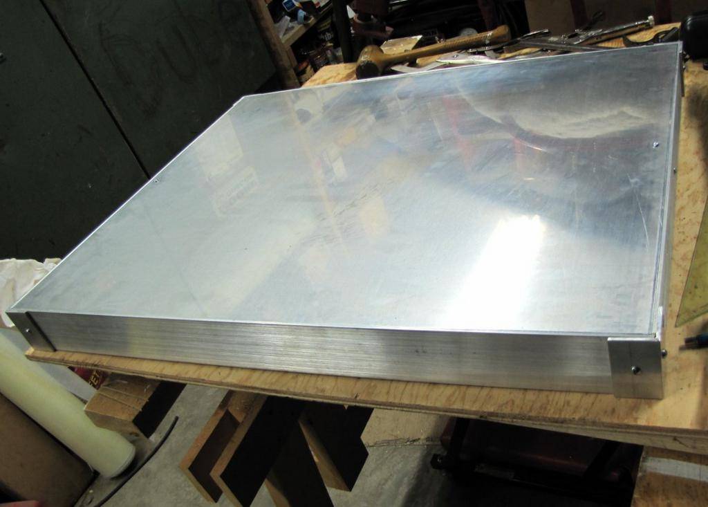
The back of the housing was laid out with the aid of a cardboard template and cut to size, the side pieces cut to length, and all of the bracketing fabricated.
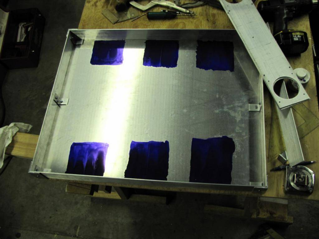
Once the housing was assembled, the fan mounting plates from the LED bars were used to lay out the locations of the five holes required for each cooling fan.
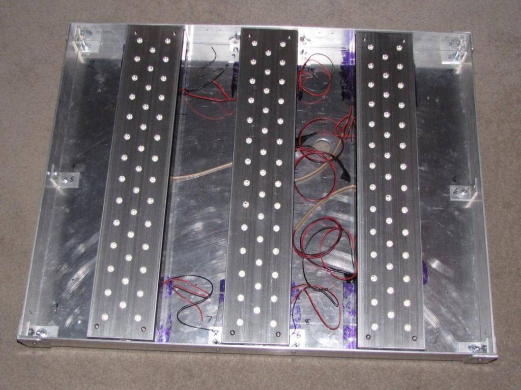
After the LED bars were located, the layout for the PL-L reflector assemblies was done. The reflector assemblies were spaced off of the backplate to provide a wiring raceway beneath them and to bring the reflectors up to the same elevation as the face of the LED bars. The fixture was completely assembled to insure that everything worked, and then it was blown apart for finishing the visible areas. The exposed surfaces were all brush finished and clear lacquer applied prior to the final assembly.
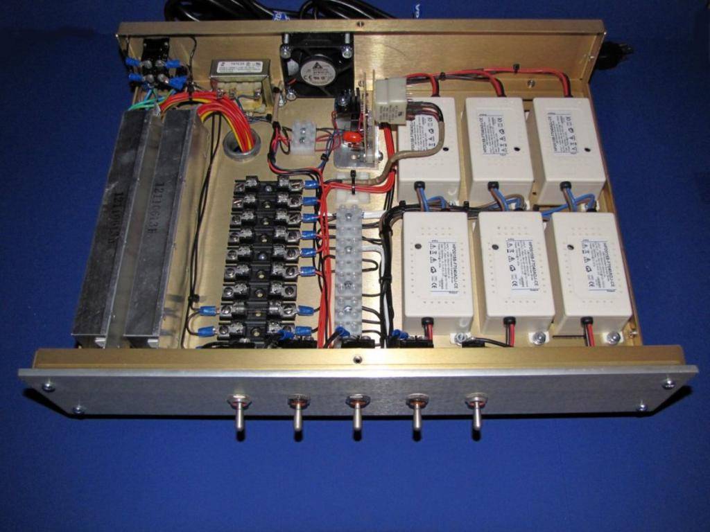
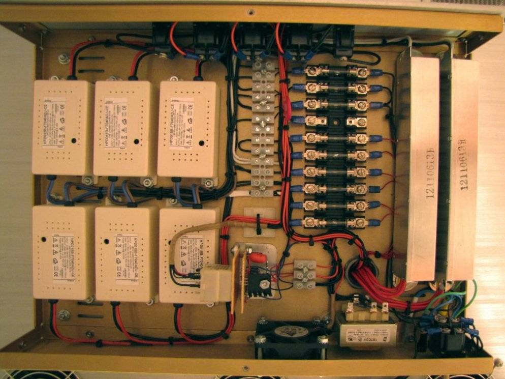
The ballast/driver enclosure is a 3” x 12” x 16” tabletop amplifier case ordered from Par-Metal. It has a gold alodine finish and the optional heavier front plate in brushed aluminum. The enclosure was the largest that Par-Metal offered in that depth, and was a snug fit for everything that found a home in it. There are six driver modules that can source from 100-700ma each. They are rated at 28 watts, but apparently can comfortably source up to around 40 watts. There are two drivers used per bar, with one driving 20 LED’s and the other driving 21. At the anticipated current levels, the drivers will be pushing from 20 to 30 watts each. The enclosure is fan-cooled and utilizes a DIY 2-stage power supply that allows the heat-sink fans and the driver enclosure fan to run at different voltages. The fan circuitry is protected with a power-loss relay that will kill the a-c power to the fixture if the fan power supply fails. I thought that I was going overboard with this level of protection, but the circuit has already proven its’ utility when the first enclosure fan died at 3 hours of usage, overheating the LM317 voltage regulator and forcing it to shut down. That is the first infancy failure of a Delta fan that I have seen.
The enclosure is also home to the ballasts for the PL-L lamps, the transformer for the fan power supply, terminal strips, and a fuse block. The primary on the ballasts is fused, as is the transformer and the supply line feeding the drivers. The driver outputs are individually fused, providing a handy test point to set the current on each driver.
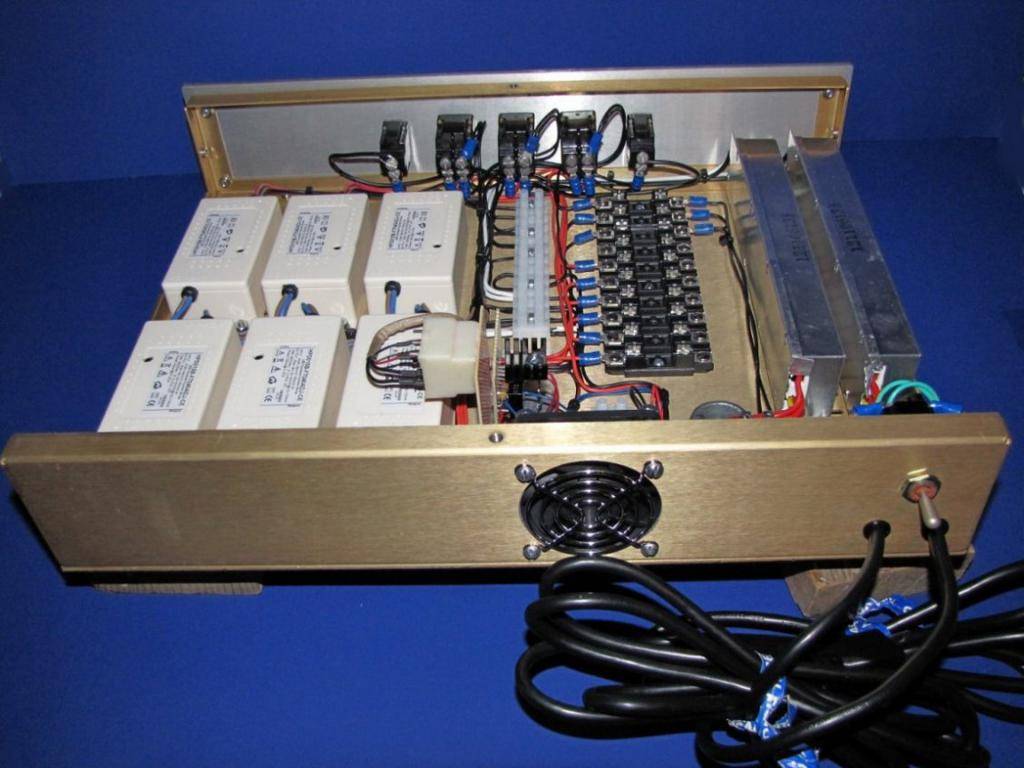
There are two power cords feeding the fixture. The main power switch on the back of the enclosure is a 3-position, double-pole, double-throw switch. This enables the selection of one cord or two, and an off position. The second cord is provided so that separate timers can be used on the two light sources in case I feel like playing with staging the lighting at the beginning and end of each “day”. The front panel switches are set up so that the first switch controls the outboard PL-Ls, the 2nd, 3rd, and 4th switch control the corresponding LED bars, and the 5th switch is for the inboard pair of PL-Ls.
Wired, installed, and running.
I hope everyone enjoyed looking at this – it was a hell of a lot of fun to build, far more expensive than I ever would have believed, and hopefully it will fulfill my expectations!
First of all, I would like to thank a couple of the people who were crucial to its development. Knna is the first one that comes to mind – his tutorials on building LED fixtures on numerous web sites was critical to my understanding of what was necessary, and although I ultimately didn’t use his assembly technique, he was the origin of my understanding the mechanics of what was required. In addition, he worked with me through numerous PM exchanges, assisting me in the evolution of thought that took me from a ”conventional” LED application with two or three spectrums to what you see here.
Shafto was another contributor to the knowledge base that brought this about – his posts on MCPCB’s and plate re-flow soldering directly contributed to the successful completion of this project. Additionally, virtually everyone that has posted about DIY LED fixtures in the last couple of years has made some contribution to this. Unfortunately, I can’t claim that the hybrid concept is wholly original – once I had the design concept in mind, I found that Old Mac had built something on the same principle several years ago, Ahhhavalanche has his Magma Chamber, and there are undoubtedly many others.
The concept was developing about the same time that some of the commercial manufacturers were starting to bring out luminaires with more than the once-standard red/blue mix. I had used a home-made 6 x 55 watt PL-L fixture, and was impressed with the results. Further research showed that the PL-L lamps in virtually all available color temperatures had a very good spectral distribution with the exception of being weak in the far-red area.
I generally grow in a SCROG format, so the somewhat limited penetration of these lamps wasn’t really an issue, and they lent themselves well to covering the entire grow area rather than a point source or the rather limited form-factor of most existing commercial LED products. I decided to combine the two technologies because it worked quite well for the form factor that I wanted to achieve and it seemed like a much more economical and effective approach to getting full spectrum lighting. Using exclusively LED’s to achieve a full spectrum is counter-intuitive to me – combining very narrow outputs to achieve a broad spectrum doesn’t make sense, and it is quite expensive if you use good components.
I decided to purchase a commercially-made fixture in order to get some experience with any peculiarities that are brought to growing with the usage of LED's, and also to take the pressure off of getting things done more quickly than I was comfortable with. After lots of research, I settled on the Lumigrow ES330, which ultimately set a pretty damn high standard for what I would build. As a retired industrial electrician, I could appreciate the construction techniques and build quality that go into that product line, and as a grower I came to appreciate how well it functioned. Ultimately, I can attest to the fact that even as expensive as the Lumigrow products are, they are a bargain! I have to thank SOTF420 for his input on that purchase.
The ES330 showed me that while it was a very effective light source, it lacked a bit in giving me an even, edge-to-edge coverage of my screen. My former PL-L fixture was far superior in that respect, so the design started to take shape in that direction. I decided to build something with a similar form-factor, but with the addition of 660nm LED’s. The final design was established as utilizing (4) 55-watt PL-L lamps interspersed with (3) LED bars of similar dimensions (4” x 22”). This gave an overall footprint of 22-1/2” x 28-1/2”, which worked well with a 30”x 30” screen.
Each LED bar is built around a heat-sink that is 4”x 22” x 1.3”, with (11) 1” tall fins, and black anodized. There are (41) Osram Golden Dragon Plus LED’s mounted on MCPCB’s glued to each one. Although I wanted a passive design to avoid fan noise, calculations showed that the heat-sinks would only support 35-40 watts without additional airflow. I didn’t want to be restricted by this if it turned out that more far-red was needed for the best spectral distribution, and there were too many limitations put on the fixture design by trying to keep the fins open for passive heat shedding. I was also concerned about the additional thermal load of the PL-L reflector assemblies mounted immediately adjacent to the sides of each bar. Reluctantly, the final design uses 7 (!) fans. There are (2) Delta 12-volt 92 x 15 mm fans turning 1800 rpm at 12vdc on each heat-sink. They are rated at 26 cfm and 25 dB’s at full voltage. These fans were set up with one pushing and one pulling, and mounted on an aluminum plate cut to match the footprint of the heat-sink. There is also a single small fan pushing air into the ballast/driver enclosure. End plates were epoxied onto the heat-sinks to keep the air properly directed. The fans also serve as standoffs for the LED bar when it is inserted into the housing, with the space between the fans providing a raceway for the wiring.
Each LED bar (with its cooling fans) is individually switched, as are the PL-L ballasts. This will allow the fixture to be lit up from the center out if that is desirable when the plants are small. With the fan-forced airflow, each bar is capable of easily pushing at least 60 watts, so the luminaire is capable of a minimum of 400 watts ((4 x 55) + (3 x 60)). The Golden Dragons have a very wide viewing angle of 170 degrees, so hopefully they will be well balanced with the distribution and penetration of the PL-L’s. This viewing angle was tightened up a bit by the cover-plate design, which blocks enough of the horizontal light distribution to keep it out of your eyes when working below the fixture but still gives good coverage across the screen.
The LED’s were mounted on the MCPCB’s using the hot plate method detailed for me by Shafto. My particular spin on this was to use an inductive hot plate with the stainless steel “interface disc” that is sold for use with standard cookware. The interface disc is ¼” thick, 8” in diameter, and has a nice handle on it. The combination worked very well – this type of hot plate heats up and cools down quickly, and while the disc would have been large enough to have done numerous components at the same time, I stuck with soldering them 6 at a time. I didn’t want them soaking up too much heat from sitting on the disc for too long before I could pick them off after they had been soldered, or spread over the disc so widely that there would be variations in the time it took to heat them up. This technique worked exceptionally well, with zero failures from the soldering process. The LED’s were positioned on the MCPCB’s freehand, using the labeling on the face of MCPCB as a rough guide for placement.
The assembled LED’s were positioned onto the heat-sink with the aid of a wooden template that was clamped to the heat-sink Holes were drilled in the template to place the loaded MCPCB’s in, with enough clearance to jockey them around a bit. This clearance, combined with the freehand placement of the LED’s, created some minor problems with getting the holes in the cover plates where they needed to be. If I were going to do this build again, I would find ways to tighten up the variation in the final placement of the components to mitigate this problem.
After the epoxy had set, the clamps were taken off and the template removed. The MCPCB’s were then wired to form 2 series strings. Soldering of the leads onto the stars was no fun – the heat-sink is both large and efficient, and trying to get things up to soldering temperature was difficult. I was glad that I had thought to tin the solder pads with liquid solder when the plate soldering process was going on, because that helped a great deal. By the time the 3rd bar was completed, my technique had improved considerably!
I had struggled with the best way to protect the components and the wiring. I didn’t want to use a clear plastic that would block some of the light, and eventually decided on an 1/8” aluminum plate with holes drilled on the same centers as the LED’s. The plate was spaced off of the surface of the heat-sink so that the LED lenses just entered the holes in the plate, and then each hole was chamfered. The chamfering provided a somewhat polished surface, hopefully acting as a crude reflector to narrow down the Golden Dragon’s 170-degree viewing angle. After all of the machine work was done on the cover plates, the surface was brush-finished with sandpaper, the counter sunk holes buffed, and a couple of coats of clear lacquer was applied. The plates were attached to the heat-sinks with #8 button-head screws and 3/16” nylon standoffs.
Somewhere in the process of fitting the cover plate, the back plate, and all of the associated drilling and tapping, I made a costly mistake. The long power leads from each end of the power circuitry had been left attached to the LED’s after the wiring and testing was complete, and had just been taped out of the way for the machine work. After the plates and fans were fastened in place, I tested the bars to admire how pretty everything looked….. and one string wouldn’t light. I checked it out, and discovered that I had blown one entire string completely to hell. The only thing that I can attribute it to is static discharge. Somehow, one of the leads came into contact with something that I wish it hadn’t – that was about a $100 screw up. Incidentally, the 2-part epoxy sold for “permanent” mounting doesn’t quite live up to its’ fearsome reputation for permanence. I was really anxious about getting the blown components off the heat-sink, but it turned out the adhesive was no match for the careful application of a sharp chisel and a ball-peen hammer.
The back of the housing was laid out with the aid of a cardboard template and cut to size, the side pieces cut to length, and all of the bracketing fabricated.
Once the housing was assembled, the fan mounting plates from the LED bars were used to lay out the locations of the five holes required for each cooling fan.
After the LED bars were located, the layout for the PL-L reflector assemblies was done. The reflector assemblies were spaced off of the backplate to provide a wiring raceway beneath them and to bring the reflectors up to the same elevation as the face of the LED bars. The fixture was completely assembled to insure that everything worked, and then it was blown apart for finishing the visible areas. The exposed surfaces were all brush finished and clear lacquer applied prior to the final assembly.
The ballast/driver enclosure is a 3” x 12” x 16” tabletop amplifier case ordered from Par-Metal. It has a gold alodine finish and the optional heavier front plate in brushed aluminum. The enclosure was the largest that Par-Metal offered in that depth, and was a snug fit for everything that found a home in it. There are six driver modules that can source from 100-700ma each. They are rated at 28 watts, but apparently can comfortably source up to around 40 watts. There are two drivers used per bar, with one driving 20 LED’s and the other driving 21. At the anticipated current levels, the drivers will be pushing from 20 to 30 watts each. The enclosure is fan-cooled and utilizes a DIY 2-stage power supply that allows the heat-sink fans and the driver enclosure fan to run at different voltages. The fan circuitry is protected with a power-loss relay that will kill the a-c power to the fixture if the fan power supply fails. I thought that I was going overboard with this level of protection, but the circuit has already proven its’ utility when the first enclosure fan died at 3 hours of usage, overheating the LM317 voltage regulator and forcing it to shut down. That is the first infancy failure of a Delta fan that I have seen.
The enclosure is also home to the ballasts for the PL-L lamps, the transformer for the fan power supply, terminal strips, and a fuse block. The primary on the ballasts is fused, as is the transformer and the supply line feeding the drivers. The driver outputs are individually fused, providing a handy test point to set the current on each driver.
There are two power cords feeding the fixture. The main power switch on the back of the enclosure is a 3-position, double-pole, double-throw switch. This enables the selection of one cord or two, and an off position. The second cord is provided so that separate timers can be used on the two light sources in case I feel like playing with staging the lighting at the beginning and end of each “day”. The front panel switches are set up so that the first switch controls the outboard PL-Ls, the 2nd, 3rd, and 4th switch control the corresponding LED bars, and the 5th switch is for the inboard pair of PL-Ls.
Wired, installed, and running.
I hope everyone enjoyed looking at this – it was a hell of a lot of fun to build, far more expensive than I ever would have believed, and hopefully it will fulfill my expectations!
Last edited:


